| Latest Maths NCERT Books Solution | ||||||
|---|---|---|---|---|---|---|
| 6th | 7th | 8th | 9th | 10th | 11th | 12th |
Chapter 2 Lines and Angles
This section offers detailed solutions for the exercises presented in Chapter 2, "Lines and Angles", from the authoritative NCERT Class 6 Ganita Prakash textbook designated for the 2024-25 academic session. These solutions are meticulously prepared to support students as they embark on exploring fundamental geometric concepts, serving as an essential guide in understanding the basic elements that structure the visual world around us. The primary focus is on building a strong conceptual foundation regarding points, lines, line segments, rays, and the pivotal concept of angles.
Within these solutions, learners will find comprehensive walkthroughs demonstrating how to accurately identify these geometric entities within various diagrams and connect them to real-world scenarios. A substantial part is dedicated to the crucial skill of understanding, classifying, and working with different types of angles. Key classifications covered include:
- Acute Angles: Those measuring less than $90^\circ$.
- Obtuse Angles: Those measuring greater than $90^\circ$ but less than $180^\circ$.
- Right Angles: Precisely measuring $90^\circ$.
- Straight Angles: Forming a straight line and measuring exactly $180^\circ$.
- Reflex Angles: Angles greater than $180^\circ$ but less than $360^\circ$.
Furthermore, the solutions delve into the relationships between lines themselves. Students will gain clarity on identifying and differentiating between parallel lines (which never intersect), intersecting lines (which cross at a single point), and perpendicular lines (which intersect at a perfect right angle, $90^\circ$). Examples and methods for recognizing these configurations in diagrams are clearly illustrated. A critical aspect addressed is the understanding of relationships between angles formed by intersecting lines. This includes:
- Complementary Angles: Pairs of angles whose measures sum up to $90^\circ$, i.e., $m\angle A + m\angle B = 90^\circ$.
- Supplementary Angles: Pairs of angles whose measures sum up to $180^\circ$, i.e., $m\angle C + m\angle D = 180^\circ$.
- Adjacent Angles: Angles sharing a common vertex and a common side but no common interior points.
- Linear Pairs: Adjacent angles whose non-common sides form a straight line, making them supplementary.
- Vertically Opposite Angles: Angles formed opposite each other when two lines intersect; these are always equal in measure.
For problems that necessitate calculations – such as determining the measure of a complementary or supplementary angle to a given angle, or finding unknown angle measures in figures involving intersecting lines – the solutions provide explicit, step-by-step algebraic procedures. Often, this involves setting up and solving simple equations based on the geometric properties discussed. By diligently working through these explanations, students will enhance their ability to interpret geometric figures with precision, apply definitions accurately, and utilize fundamental angle properties as tools for problem-solving. This resource acts as a vital aid in developing foundational spatial reasoning and precision in geometric thinking, ensuring students solidify their understanding of the essential building blocks of geometry introduced in this chapter of the Class 6 Ganita Prakash (NCERT 2024-25) curriculum.
Figure it Out (Page 15 - 17)
Rihan marked a point on a piece of paper. How many lines can he draw that pass through the point?
Sheetal marked two points on a piece of paper. How many different lines can she draw that pass through both of the points?
Can you help Rihan and Sheetal find their answers?Answer:
Let's help Rihan and Sheetal find their answers based on the principles of geometry.
For Rihan's question:
Rihan marked a single point on a piece of paper. He wants to know how many lines can be drawn that pass through this one specific point.
Imagine the point as a tiny dot. You can draw a line that goes through this dot horizontally, vertically, or at any angle you can think of. There is no limit to the number of directions a line can extend from a single point while still passing through it.
So, Rihan can draw an infinite number of lines that pass through the point he marked.
For Sheetal's question:
Sheetal marked two distinct points on a piece of paper. She wants to know how many *different* lines can be drawn that pass through *both* of these points.
Imagine the two points as dots. If you want to draw a straight line that connects these two dots, there is only one way to do it. If you try to draw another straight line that also goes through both points, it will lie exactly on top of the first line. It won't be a different line.
This is a fundamental principle in geometry, often stated as: "Through any two distinct points, there is exactly one unique straight line."
So, Sheetal can draw only one different line that passes through both of the points she marked.
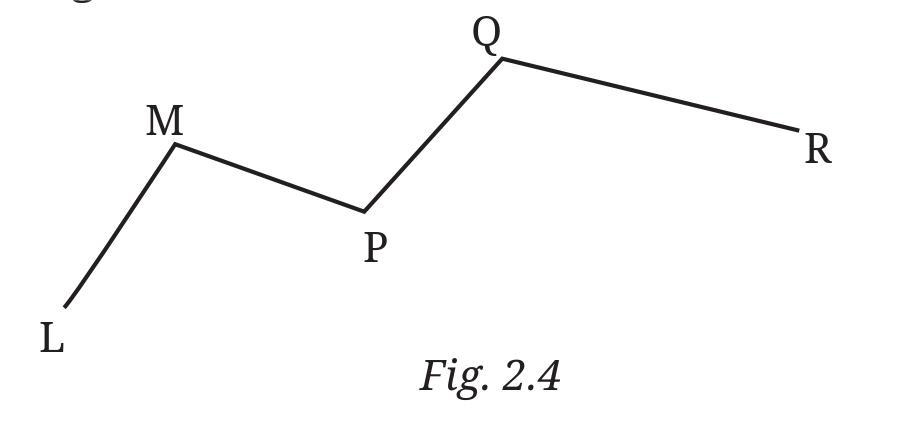
Answer:
Based on the figure provided (Fig. 2.4):
The line segments in Fig. 2.4 are the straight connections between the marked points. They are:
- Line segment AB
- Line segment BC
- Line segment CD
- Line segment DE
Now let's examine each of the five marked points (A, B, C, D, E) and see how many of these listed line segments they are on.
Points on exactly one of the line segments:
- Point A is an endpoint of line segment AB. It is not an endpoint or on the interior of BC, CD, or DE. So, A is on exactly one line segment.
- Point E is an endpoint of line segment DE. It is not an endpoint or on the interior of AB, BC, or CD. So, E is on exactly one line segment.
The marked points that are on exactly one of the line segments are A and E.
Points on two of the line segments:
- Point B is an endpoint of line segment AB and also an endpoint of line segment BC. So, B is on two line segments.
- Point C is an endpoint of line segment BC and also an endpoint of line segment CD. So, C is on two line segments.
- Point D is an endpoint of line segment CD and also an endpoint of line segment DE. So, D is on two line segments.
The marked points that are on two of the line segments are B, C, and D.
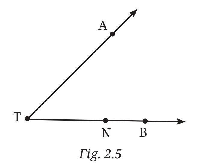
Answer:
A ray is a part of a line that starts at a particular point (called the starting point or endpoint) and extends infinitely in one direction.
Based on the figure, several rays can be identified with T as their starting point:
- Ray TU (starts at T and passes through U)
- Ray TV (starts at T and passes through V)
- Ray TW (starts at T and passes through W)
- Ray TX (starts at T and passes through X)
There are also other rays that can be identified if we consider other points as starting points (like Ray UT, Ray WT, etc.), but the question seems focused on rays originating from T.
Is T the starting point of each of these rays (TU, TV, TW, TX)?
Yes, based on how these specific rays are named (starting with T), T is the starting point of each of these rays.
a. $\overleftrightarrow{OP}$ and $\overleftrightarrow{OQ}$ meet at O.
b. $\overrightarrow{XY}$ and $\overleftrightarrow{PQ}$ intersect at point M.
c. Line $l$ contains points E and F but not point D.
d. Point P lies on AB.
Answer:
Here are the descriptions for drawing the rough figures for each statement:
a. $\overleftrightarrow{OP}$ and $\overleftrightarrow{OQ}$ meet at O.
Figure Description: Draw a point and label it O. Draw a straight line that passes through O and extends infinitely in both directions. Label another point on this line as P. This represents line $\overleftrightarrow{OP}$. Now, draw another straight line that also passes through point O but goes in a different direction from $\overleftrightarrow{OP}$. Label a point on this second line as Q. This represents line $\overleftrightarrow{OQ}$. The two lines share the point O, which is where they meet or intersect.
b. $\overrightarrow{XY}$ and $\overleftrightarrow{PQ}$ intersect at point M.
Figure Description: Draw a point and label it X. Draw a straight line starting from X and passing through another point labeled Y, extending infinitely beyond Y. This represents ray $\overrightarrow{XY}$. Now, draw a straight line that passes through two points labeled P and Q, extending infinitely in both directions. This represents line $\overleftrightarrow{PQ}$. Draw these two shapes such that they cross each other at a single point. Label this intersection point as M.
c. Line $l$ contains points E and F but not point D.
Figure Description: Draw a straight line and label it 'l'. Place two points on this line and label them E and F. Now, place another point somewhere else on the paper, not on the line $l$, and label it D.
d. Point P lies on AB.
Figure Description: Draw a line segment or a line with endpoints A and B (or passing through A and B). Mark a point P that is located on the line segment AB (or on the line passing through A and B). P can be between A and B, or it could be A or B themselves if the statement implies "on the line AB". Assuming it means the line segment, place P between A and B.
a. Five points
b. A line
c. Four rays
d. Five line segments
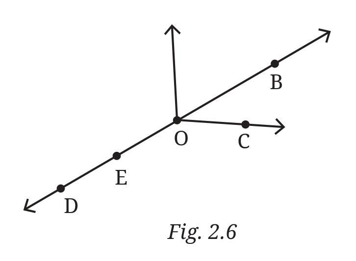
Answer:
Based on the figure (Fig. 2.6):
a. Five points:
The points marked in the figure are D, E, O, B, C.
b. A line:
The figure shows a straight line passing through points D, E, O, B, and C, with arrows indicating it extends infinitely in both directions. This line can be named using any two points on it. Some possible names are:
$\overleftrightarrow{DB}$, $\overleftrightarrow{DC}$, $\overleftrightarrow{EB}$, $\overleftrightarrow{EC}$, $\overleftrightarrow{DO}$, $\overleftrightarrow{DE}$, $\overleftrightarrow{EO}$, $\overleftrightarrow{OB}$, $\overleftrightarrow{OC}$, $\overleftrightarrow{BC}$.
We can name it as $\overleftrightarrow{DB}$.
c. Four rays:
A ray starts at a point and extends infinitely in one direction. Rays originating from point O are:
- Ray starting at O and passing through C: $\overrightarrow{OC}$
- Ray starting at O and passing through B: $\overrightarrow{OB}$
- Ray starting at O and passing through E: $\overrightarrow{OE}$
- Ray starting at O and passing through D: $\overrightarrow{OD}$
Other rays also exist, such as $\overrightarrow{ED}$ (starting at E, going towards D), $\overrightarrow{EB}$ (starting at E, going towards B), etc.
d. Five line segments:
A line segment connects two points. We can name segments formed by the marked points:
- Segment connecting D and E: DE
- Segment connecting E and O: EO
- Segment connecting O and B: OB
- Segment connecting B and C: BC
- Segment connecting D and B: DB
Other possible line segments include DC, EB, EC, DO, OC, etc.
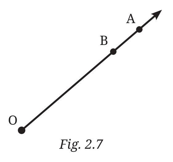
a. Can you also name it as $\overrightarrow{OB}$ ? Why?
b. Can we write $\overrightarrow{OA}$ as $\overrightarrow{AO}$ ? Why or why not?
Answer:
Let's analyze the ray $\overrightarrow{OA}$ based on the figure (Fig. 2.7).
a. Can you also name it as $\overrightarrow{OB}$ ? Why?
Yes, you can also name the ray $\overrightarrow{OA}$ as $\overrightarrow{OB}$.
Explanation: A ray is named by its starting point followed by another point on the ray that indicates the direction. Both $\overrightarrow{OA}$ and $\overrightarrow{OB}$ start at the point O. The figure shows that point B lies on the ray that starts at O and passes through A, extending in the same direction. Since both rays start at O and extend in the same direction (containing both A and B), they represent the same ray. Therefore, $\overrightarrow{OA}$ and $\overrightarrow{OB}$ are two different names for the same ray.
b. Can we write $\overrightarrow{OA}$ as $\overrightarrow{AO}$ ? Why or why not?
No, we cannot write $\overrightarrow{OA}$ as $\overrightarrow{AO}$.
Explanation: The order of the points in the name of a ray is very important. The first letter always represents the starting point (endpoint) of the ray, and the second letter represents a point that the ray passes through, indicating its direction.
- $\overrightarrow{OA}$ starts at point O and extends infinitely through point A.
- $\overrightarrow{AO}$ starts at point A and extends infinitely through point O (in the opposite direction of $\overrightarrow{OA}$).
Since these two rays have different starting points (O for $\overrightarrow{OA}$ and A for $\overrightarrow{AO}$) and extend in opposite directions along the line, they are different rays. Therefore, $\overrightarrow{OA}$ is not the same as $\overrightarrow{AO}$.
Intext Question (Page 17 - 18)
Vidya has just opened her book. Let us observe her opening the cover of the book in different scenarios.
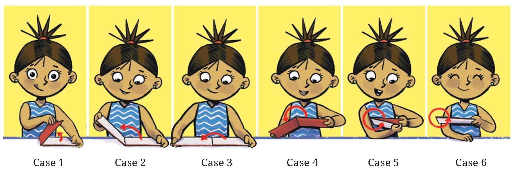
Question: Do you see angles being made in each of these cases? Can you mark their arms and vertex?
Answer:
Yes, in each of these cases where Vidya is opening the cover of the book, angles are being made.
An angle is formed by two rays (or line segments) that share a common endpoint called the vertex. In the case of the book cover opening:
The vertex of the angle is located along the spine of the book. Any point along the line of the spine where the two covers are joined can be considered a vertex.
The arms (or sides) of the angle are the edges or surfaces of the two book covers that meet at the spine. As the book is opened wider, the angle between these arms increases.
In the first scenario (closed book), the angle is very small, close to $0^\circ$. In the second and third scenarios (partially and more open book), distinct angles are clearly formed between the covers.
Figure it Out (Page 19 - 21)


Answer:
Yes, angles can be found in many places within the given pictures.
In the picture showing the furniture (table and chairs), angles are formed at the corners of the table and the chair seats, at the joints where legs meet the tops, and where the backrests meet the seats or legs.
In the picture showing the clock, angles are formed by the hands of the clock (the hour hand, the minute hand, and potentially the second hand) meeting at the center of the clock face. Angles are also present at the corners of the square clock frame.
Let's choose an angle from the clock face to illustrate:
Consider the angle formed by the hour hand and the minute hand.
Drawing the rays and naming the vertex:
- Draw a point in the center of your paper. Label this point O. This point represents the center of the clock face. This is the vertex of the angle.
- Draw a ray starting from point O and extending outwards along the hour hand. Label a point on this ray (away from O) as H. This represents the ray along the hour hand, $\overrightarrow{OH}$. This is one arm of the angle.
- Draw another ray starting from point O and extending outwards along the minute hand. Label a point on this ray (away from O) as M. This represents the ray along the minute hand, $\overrightarrow{OM}$. This is the other arm of the angle.
The angle formed is $\angle HOM$ or $\angle MOH$. The vertex is O.
Question 2. Draw and label an angle with arms ST and SR.
Answer:
To draw an angle with arms ST and SR, the common starting point of the two rays (or segments) must be S. This point S is the vertex of the angle.
Drawing and labeling the angle:
- Draw a point and label it S. This is the vertex.
- Draw a ray starting from S and extending in one direction. Label a point on this ray (other than S) as T. This represents the arm $\overrightarrow{ST}$.
- Draw another ray starting from S and extending in a different direction from $\overrightarrow{ST}$. Label a point on this ray (other than S) as R. This represents the arm $\overrightarrow{SR}$.
The angle formed is $\angle TSR$ or $\angle RST$. The vertex is S, and the arms are ray ST and ray SR.
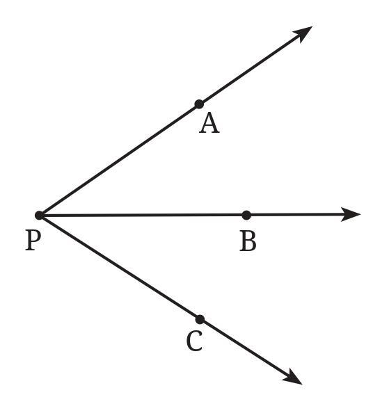
Answer:
In geometry, an angle can sometimes be named using just its vertex letter if that vertex is the common endpoint for only two rays forming a single angle. However, if multiple rays originate from the same vertex, creating several different angles, simply using the vertex letter becomes ambiguous.
In the given figure (Fig. 2.8), point P is the vertex where several rays meet: $\overrightarrow{PA}$, $\overrightarrow{PB}$, $\overrightarrow{PC}$, and $\overrightarrow{PD}$. These rays form multiple distinct angles at the vertex P, such as:
- $\angle$APB
- $\angle$BPC
- $\angle$CPD
- $\angle$APC
- $\angle$BPD
- $\angle$APD
- ... and potentially more if other points existed on the rays.
The notation $\angle$APC specifically refers to the angle formed by the rays $\overrightarrow{PA}$ and $\overrightarrow{PC}$. If we were to simply write $\angle$P, it would not be clear which of the several angles at vertex P is being referenced. It could mean $\angle$APB, $\angle$BPC, $\angle$APC, or any other angle with vertex P.
Therefore, to avoid confusion and clearly identify the specific angle, we must use the three-point notation $\angle$APC, where the vertex (P) is the middle letter.
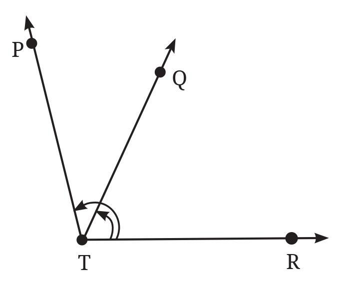
Answer:
Based on the given figure (Fig. 2.9), the angles marked with arcs are located at the vertices B, C, D, and E.
We name each angle using three points, with the vertex in the middle, and one point from each arm of the angle.
The angles marked are:
- Angle with vertex B, formed by rays $\overrightarrow{BA}$ and $\overrightarrow{BC}$: $\angle$ABC
- Angle with vertex C, formed by rays $\overrightarrow{CB}$ and $\overrightarrow{CD}$: $\angle$BCD
- Angle with vertex D, formed by rays $\overrightarrow{DC}$ and $\overrightarrow{DE}$: $\angle$CDE
- Angle with vertex E, formed by rays $\overrightarrow{ED}$ and $\overrightarrow{EA}$: $\angle$DEA
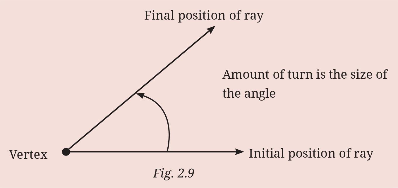
Question 5. Mark any three points on your paper that are not on one line. Label them A, B, C. Draw all possible lines going through pairs of these points. How many lines do you get? Name them. How many angles can you name using A, B, C? Write them down, and mark each of them with a curve as in Fig. 2.9.
Answer:
Let's follow the steps outlined in the question.
Step 1: Mark three points A, B, C that are not on one line.
Description: On a piece of paper, draw three dots such that they do not lie in a single straight line. Label these dots A, B, and C. For example, you could draw them forming a triangle.
Step 2: Draw all possible lines going through pairs of these points.
Description: Draw a straight line that passes through points A and B, extending infinitely in both directions. Draw another straight line that passes through points B and C, extending infinitely. Draw a third straight line that passes through points C and A, extending infinitely.
How many lines do you get?
Since the three points are not on the same line, drawing a line through each unique pair of points will result in distinct lines.
Possible pairs of points are (A, B), (B, C), and (C, A).
Drawing a line through each pair gives us 3 distinct lines.
You get 3 lines.
Name the lines:
The lines can be named using the two points they pass through. Using the notation for a line:
- Line through A and B: $\overleftrightarrow{AB}$ (or $\overleftrightarrow{BA}$)
- Line through B and C: $\overleftrightarrow{BC}$ (or $\overleftrightarrow{CB}$)
- Line through C and A: $\overleftrightarrow{CA}$ (or $\overleftrightarrow{AC}$)
How many angles can you name using A, B, C? Write them down, and mark each of them with a curve.
An angle is formed when two rays share a common endpoint (vertex). Using the three points A, B, and C, we can form angles where one of the points is the vertex, and the other two points lie on the arms (rays) of the angle.
The possible vertices are A, B, and C.
- Angle at vertex A: The arms are the rays starting at A and passing through B and C. This angle is named $\angle$BAC or $\angle$CAB.
- Angle at vertex B: The arms are the rays starting at B and passing through A and C. This angle is named $\angle$ABC or $\angle$CBA.
- Angle at vertex C: The arms are the rays starting at C and passing through A and B. This angle is named $\angle$BCA or $\angle$ACB.
There are 3 angles that can be named using points A, B, and C as the vertex and points on the arms.
The angles are:
- $\angle$BAC (or $\angle$CAB) - Vertex A, Arms $\overrightarrow{AB}$ and $\overrightarrow{AC}$
- $\angle$ABC (or $\angle$CBA) - Vertex B, Arms $\overrightarrow{BA}$ and $\overrightarrow{BC}$
- $\angle$BCA (or $\angle$ACB) - Vertex C, Arms $\overrightarrow{CA}$ and $\overrightarrow{CB}$
Marking with a curve:
Description: On your drawing of the three points A, B, C and the lines connecting them, use a curved line to mark each of these three angles. For $\angle$BAC, draw a curve between the arms $\overrightarrow{AB}$ and $\overrightarrow{AC}$ near the vertex A. Similarly, draw a curve for $\angle$ABC near vertex B (between arms $\overrightarrow{BA}$ and $\overrightarrow{BC}$), and for $\angle$BCA near vertex C (between arms $\overrightarrow{CA}$ and $\overrightarrow{CB}$). This is similar to how the angles are marked in Fig. 2.9.
Question 6. Now mark any four points on your paper so that no three of them are on one line. Label them A, B, C, D. Draw all possible lines going through pairs of these points. How many lines do you get? Name them. How many angles can you name using A, B, C, D? Write them all down, and mark each of them with a curve as in Fig. 2.9.
Answer:
Let's follow the steps outlined in the question for four points, no three of which are on one line.
Step 1: Mark four points A, B, C, D so that no three of them are on one line.
Description: On a piece of paper, draw four dots such that no three of them fall on the same straight line. For example, you could draw them as the four vertices of a quadrilateral (like a square, a general rectangle, or just four points forming a shape that isn't a triangle with an extra point on one side). Label these dots A, B, C, and D.
Step 2: Draw all possible lines going through pairs of these points.
Description: Draw a straight line that passes through points A and B, extending infinitely in both directions. Do the same for points A and C, A and D, B and C, B and D, and C and D.
How many lines do you get?
Since no three points are collinear, each pair of points defines a unique straight line. We need to count the number of unique pairs of points from a set of 4 points.
The possible pairs are (A, B), (A, C), (A, D), (B, C), (B, D), (C, D).
Counting these pairs, we find there are 6 unique pairs.
Thus, you get 6 different lines.
Name the lines:
Using the notation for a line with two points it passes through:
- Line through A and B: $\overleftrightarrow{AB}$ (or $\overleftrightarrow{BA}$)
- Line through A and C: $\overleftrightarrow{AC}$ (or $\overleftrightarrow{CA}$)
- Line through A and D: $\overleftrightarrow{AD}$ (or $\overleftrightarrow{DA}$)
- Line through B and C: $\overleftrightarrow{BC}$ (or $\overleftrightarrow{CB}$)
- Line through B and D: $\overleftrightarrow{BD}$ (or $\overleftrightarrow{DB}$)
- Line through C and D: $\overleftrightarrow{CD}$ (or $\overleftrightarrow{DC}$)
How many angles can you name using A, B, C, D? Write them all down, and mark each of them with a curve.
An angle requires a vertex and two arms (rays) originating from that vertex. Using the points A, B, C, D, each of these points can serve as a vertex. The arms of the angle will be rays starting from the vertex and passing through two other distinct points from the set {A, B, C, D}.
Let's list the angles based on the vertex:
- Angles with vertex A: Arms are rays $\overrightarrow{AB}$, $\overrightarrow{AC}$, $\overrightarrow{AD}$. Angles are $\angle$BAC, $\angle$BAD, $\angle$CAD. (3 angles)
- Angles with vertex B: Arms are rays $\overrightarrow{BA}$, $\overrightarrow{BC}$, $\overrightarrow{BD}$. Angles are $\angle$ABC, $\angle$ABD, $\angle$CBD. (3 angles)
- Angles with vertex C: Arms are rays $\overrightarrow{CA}$, $\overrightarrow{CB}$, $\overrightarrow{CD}$. Angles are $\angle$ACB, $\angle$ACD, $\angle$BCD. (3 angles)
- Angles with vertex D: Arms are rays $\overrightarrow{DA}$, $\overrightarrow{DB}$, $\overrightarrow{DC}$. Angles are $\angle$ADB, $\angle$ADC, $\angle$BDC. (3 angles)
Adding these up, we get a total of $3 + 3 + 3 + 3 = 12$ angles.
You can name 12 angles using points A, B, C, and D.
The angles are:
- At Vertex A: $\angle$BAC, $\angle$BAD, $\angle$CAD
- At Vertex B: $\angle$ABC, $\angle$ABD, $\angle$CBD
- At Vertex C: $\angle$ACB, $\angle$ACD, $\angle$BCD
- At Vertex D: $\angle$ADB, $\angle$ADC, $\angle$BDC
Marking with a curve:
Description: On your drawing of the four points and the lines connecting them, use a curved line to mark each of these 12 angles. For example, near vertex A, draw curves between the rays $\overrightarrow{AB}$ and $\overrightarrow{AC}$ to mark $\angle$BAC, between $\overrightarrow{AB}$ and $\overrightarrow{AD}$ to mark $\angle$BAD, and between $\overrightarrow{AC}$ and $\overrightarrow{AD}$ to mark $\angle$CAD. Repeat this process for the angles at vertices B, C, and D.
Figure it Out (Page 23)
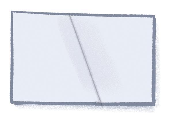
Answer:
Let's perform the folding activity and observe the angles formed.
Part 1: Folding a rectangular sheet and drawing a line along the fold.
When you fold a rectangular sheet of paper and draw a line along the fold, this line (the fold line) will intersect the edges of the rectangular paper. The angles formed between this fold line and the sides (edges) of the paper depend on how you make the fold.
If you fold the paper so that the fold line is, for example, perpendicular to one of the long sides, then the angle formed between the fold and that long side will be $90^\circ$. If the fold is not perpendicular, it will form angles that are either acute (less than $90^\circ$) or obtuse (greater than $90^\circ$) where the fold meets the edge.
Consider a fold line that cuts across the paper from one edge to another. At the point where the fold line meets an edge of the paper, it forms two angles on either side of the fold line on that edge. These two angles are supplementary (they add up to $180^\circ$) if the edge is a straight line.
Part 2: Making different angles by folding and comparing them.
By folding the paper in different ways, you can create fold lines that make various angles with the sides of the paper or create angles within the paper itself (like folding a corner onto an edge, which bisects an angle). Each different fold will result in angles of different sizes.
- Fold the paper exactly in half, parallel to a side. The fold line will be parallel to two sides and perpendicular to the other two. The angles formed at the intersection with the perpendicular sides are $90^\circ$.
- Fold a corner of the paper onto the opposite side. The fold line will cut across the paper diagonally. The angles formed where this fold meets the edges will likely be acute and obtuse.
- Fold the paper multiple times. Each fold introduces new lines that intersect existing lines or edges, creating more angles.
By experimenting with different folds, you can visually compare the sizes of the angles formed. An angle that appears "sharper" or "pointier" is smaller, while an angle that appears "wider" is larger.
Which is the largest and smallest angle you made?
Through folding, you can create a wide range of angles:
- The smallest angle you can make (that is not zero) is achieved by making a fold line that is very close to parallel to an existing edge, or by making a fold that is almost perfectly aligned with an existing line. This results in an angle that is very close to $0^\circ$. Physically, you can't make a perfect $0^\circ$ angle with a fold (as it would mean no fold was made), but you can get very close.
- The largest angle you can make (that is not a straight line) is achieved by opening a fold wide, approaching a straight line. If you consider the angles formed between the fold line and the side at the edge, the largest angle you can create approaches $180^\circ$ (by making a fold almost perfectly aligned with an existing edge or line). Similar to the smallest angle, a perfect $180^\circ$ angle (a straight line fold along an edge) might not be considered an "angle made by the fold" in the context of two distinct arms, but visually, you can create an angle that is very close to $180^\circ$.
- If you fold the paper to create an angle inside (like folding a corner), the smallest angle will be greater than $0^\circ$ and the largest will be less than $180^\circ$. The angles at the corners of the rectangle itself are $90^\circ$.
In summary, by manipulating the paper through folding, you can create angles ranging from very small values (approaching $0^\circ$) to very large values (approaching $180^\circ$).
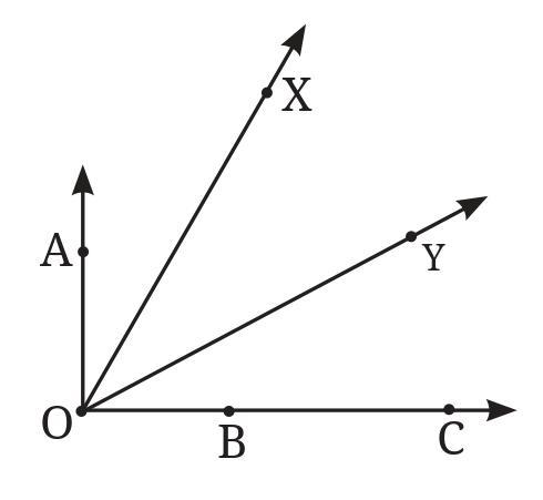
a. ∠AOB or ∠XOY
b. ∠AOB or ∠XOB
c. ∠XOB or ∠XOC
Discuss with your friends on how you decided which one is greater.
Answer:
Comparing the size of angles is done by looking at the amount of "opening" between the two arms of the angle. The length of the arms does not determine the size of the angle. We can visually compare the angles in the given figure (Fig. 2.11).
a. ∠AOB or ∠XOY
To determine which angle is greater, we need to visually compare the openings of $\angle$AOB and $\angle$XOY in the figure. One angle's opening will appear wider than the other.
Based on typical diagrams for this question, $\angle$XOY is usually drawn with a wider opening than $\angle$AOB.
Therefore, ∠XOY is greater than ∠AOB because its opening is wider.
b. ∠AOB or ∠XOB
These two angles share a common arm, OB. Both angles also have the same vertex, O.
- ∠AOB is formed by rays $\overrightarrow{OA}$ and $\overrightarrow{OB}$.
- ∠XOB is formed by rays $\overrightarrow{OX}$ and $\overrightarrow{OB}$.
Looking at the figure, ray $\overrightarrow{OA}$ lies within the interior of the angle $\angle$XOB (assuming O, X, A, B are arranged in a common sequence like X-A-B around O). This means that $\angle$XOB is composed of two smaller angles, $\angle$XOA and $\angle$AOB.
$\angle$XOB = $\angle$XOA + $\angle$AOB
Since $\angle$XOA is a positive angle (its opening is greater than zero), $\angle$XOB must be larger than $\angle$AOB.
Therefore, ∠XOB is greater than ∠AOB because $\angle$AOB is a part of $\angle$XOB.
c. ∠XOB or ∠XOC
These two angles share a common arm, OX. Both angles also have the same vertex, O.
- ∠XOB is formed by rays $\overrightarrow{OX}$ and $\overrightarrow{OB}$.
- ∠XOC is formed by rays $\overrightarrow{OX}$ and $\overrightarrow{OC}$.
Looking at the figure, ray $\overrightarrow{OB}$ lies within the interior of the angle $\angle$XOC (assuming O, X, B, C are arranged in a common sequence like X-B-C around O). This means that $\angle$XOC is composed of two smaller angles, $\angle$XOB and $\angle$BOC.
$\angle$XOC = $\angle$XOB + $\angle$BOC
Since $\angle$BOC is a positive angle, $\angle$XOC must be larger than $\angle$XOB.
Therefore, ∠XOC is greater than ∠XOB because $\angle$XOB is a part of $\angle$XOC.
Discuss with your friends on how you decided which one is greater:
When discussing with friends, we would explain that the size of an angle is about how much the arms are spread apart, not how long the lines are. We can visually see which angle has a wider opening. For angles that share an arm and a vertex (like in parts b and c), if one angle's arms enclose the arms of the other angle, the larger angle is the one that contains the smaller angle within its boundaries. We can imagine "fitting" the smaller angle inside the larger one, or seeing if a ray of one angle lies between the rays of another angle.
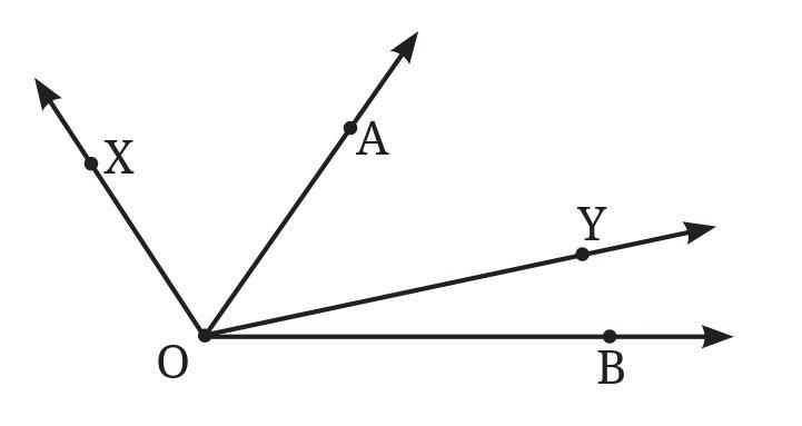
Answer:
To determine which angle is greater between $\angle$XOY and $\angle$AOB, we need to compare their sizes based on the visual representation in Fig. 2.12.
The size of an angle is determined by the amount of rotation or opening between its two arms, not by the length of the arms.
Looking at the figure:
- $\angle$XOY is the angle formed by rays $\overrightarrow{OX}$ and $\overrightarrow{OY}$, with vertex O.
- $\angle$AOB is the angle formed by rays $\overrightarrow{OA}$ and $\overrightarrow{OB}$, with vertex O.
Visually comparing the opening between the arms of $\angle$XOY and $\angle$AOB, it is clear that the space between $\overrightarrow{OA}$ and $\overrightarrow{OB}$ is wider than the space between $\overrightarrow{OX}$ and $\overrightarrow{OY}$.
Therefore, ∠AOB is greater than ∠XOY.
Reasons:
1. Visual Comparison: The opening of $\angle$AOB is visibly larger than the opening of $\angle$XOY.
2. Containment (if applicable based on point arrangement): In the figure, the ray $\overrightarrow{OY}$ appears to lie in the interior of $\angle$AOB. If a ray from the vertex lies inside another angle, it divides the larger angle into two smaller angles. In this case, $\angle$AOB can be considered as the sum of $\angle$AOY and $\angle$YOB (assuming the points are ordered in a way that makes sense, e.g., Y is between the rays OA and OB). However, a simpler reason is to note that $\angle$XOY is entirely contained within $\angle$AOB (meaning ray OX is between OA and OY, and ray OY is between OX and OB, or simply that the region defined by $\angle$XOY is a subset of the region defined by $\angle$AOB). This directly implies that $\angle$AOB is larger than $\angle$XOY.
If $\overrightarrow{OY}$ is in the interior of $\angle$AOB, then $\angle$AOB = $\angle$AOY + $\angle$YOB. Since $\angle$YOB > 0, $\angle$AOB > $\angle$AOY.
If $\overrightarrow{OX}$ is in the interior of $\angle$AOY, then $\angle$AOY = $\angle$AOX + $\angle$XOY. So $\angle$AOY > $\angle$XOY.
Thus, $\angle$AOB > $\angle$AOY > $\angle$XOY.
Intext Question (Page 28)

Let us consider a straight angle ∠AOB. Observe that any ray $\overrightarrow{OC}$ divides it into two angles, ∠AOC and ∠COB.
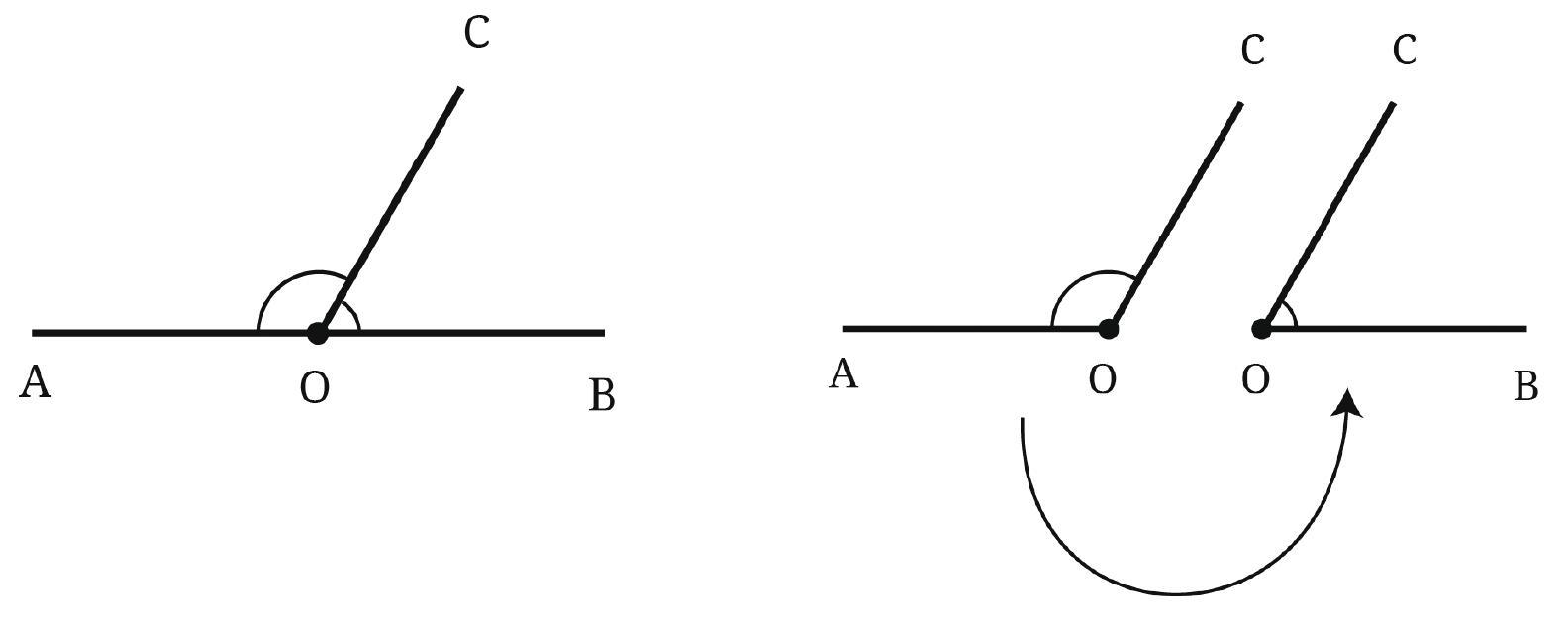
Question: Is it possible to draw $\overrightarrow{OC}$ such that the two angles are equal to each other in size?
Answer:
Yes, it is possible to draw the ray $\overrightarrow{OC}$ such that the two angles $\angle$AOC and $\angle$COB are equal to each other in size.
A straight angle $\angle$AOB measures $180^\circ$. When a ray $\overrightarrow{OC}$ is drawn starting from the vertex O and lying between the arms OA and OB, it divides the straight angle into two adjacent angles, $\angle$AOC and $\angle$COB.
The sum of these two adjacent angles is equal to the straight angle:
$\angle$AOC + $\angle$COB = $\angle$AOB
$\angle$AOC + $\angle$COB = $180^\circ$
We are asked if it is possible for $\angle$AOC and $\angle$COB to be equal in size. Let's assume they are equal. Let the size of each angle be $x$.
So, $x = \angle$AOC and $x = \angle$COB.
Substituting this into the sum equation:
$x + x = 180^\circ$
$2x = 180^\circ$
Solving for $x$:
$x = \frac{180^\circ}{2}$
$x = 90^\circ$
This means that if the two angles are equal, each angle must measure $90^\circ$. An angle that measures $90^\circ$ is called a right angle.
Drawing a ray $\overrightarrow{OC}$ such that $\angle$AOC = $90^\circ$ and $\angle$COB = $90^\circ$ is possible. This ray would be perpendicular to the line AB at the point O.
So, the ray $\overrightarrow{OC}$ can be drawn such that it is perpendicular to the line segment AB at O. When drawn this way, it divides the straight angle into two equal angles, both measuring $90^\circ$.
Figure it Out (Page 29 - 31)
Question 1. How many right angles do the windows of your classroom contain? Do you see other right angles in your classroom?
Answer:
Answer:
The number of right angles in the windows of a classroom varies depending on the design of the windows.
If the windows have rectangular or square panes, each pane will form 4 right angles at its corners.
To determine the total number of right angles in the windows, you would need to observe and count all the corners that form a $90^\circ$ angle in all the window panes combined.
Yes, there are usually many other objects in a classroom that contain right angles.
Some common examples of other right angles found in a classroom are:
- The corners of the door and its frame.
- The corners of the whiteboard or blackboard.
- The corners of student desks and the teacher's table.
- The places where the walls meet the floor or the ceiling.
- The corners of books, notebooks, and examination pads.
- The corners of cupboards, shelves, and filing cabinets.
- The corners of posters, charts, or picture frames on the walls.
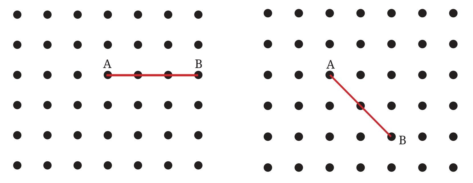
Answer:
A straight angle is an angle that measures $180^\circ$. A straight line is often considered to form a straight angle.
The question asks us to join point A to other grid points in the figure using a straight line, where each such line represents a straight angle. The "different ways" refer to the number of distinct straight lines that can be drawn starting from point A and passing through at least one other grid point shown in the figure.
We need to identify all the unique straight lines that pass through point A and connect it to another grid point within the given grid boundaries.
We can classify the straight lines based on their orientation relative to point A:
1. Horizontal Line: A straight line connecting A to any other grid point lying on the same horizontal line as A. All these points are collinear, forming a single horizontal line.
2. Vertical Line: A straight line connecting A to any other grid point lying on the same vertical line as A. All these points are collinear, forming a single vertical line.
3. Diagonal Lines: Straight lines connecting A to grid points that are not on the same horizontal or vertical line. Each distinct diagonal direction (or slope) from A corresponds to a unique diagonal line.
By examining the grid provided in the figure, we can count the number of distinct lines passing through A and at least one other grid point within the figure's boundary.
Counting the distinct lines from A to other grid points:
- There is 1 distinct horizontal line passing through A and the grid points to its right.
- There is 1 distinct vertical line passing through A and the grid points above and below it in the same column.
- By carefully counting the unique slopes formed by connecting A to every other grid point in the figure, we find that there are:
- 9 distinct diagonal lines with positive slopes.
- 6 distinct diagonal lines with negative slopes.
The total number of different ways to join A to other grid points by a straight line is the sum of the distinct horizontal, vertical, and diagonal lines.
Total number of ways = (Horizontal Lines) + (Vertical Lines) + (Distinct Diagonal Lines)
Total number of ways = $1 + 1 + (9 + 6) = 1 + 1 + 15 = 17$.
Thus, there are 17 different ways of joining A to other grid points in the figure by a straight line to get a straight angle.
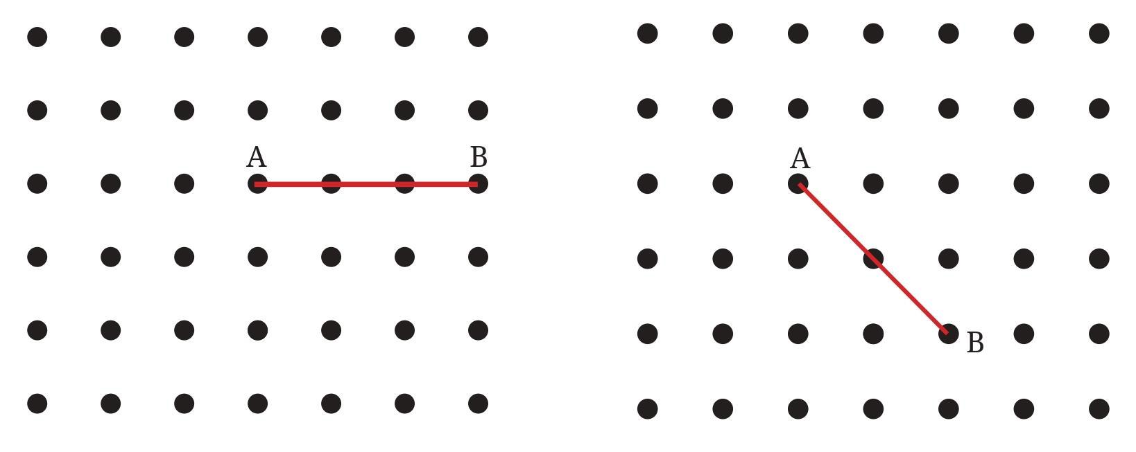
Hint: Extend the line further as shown in the figure below. To get a right angle at A, we need to draw a line through it that divides the straight angle CAB into two equal parts.
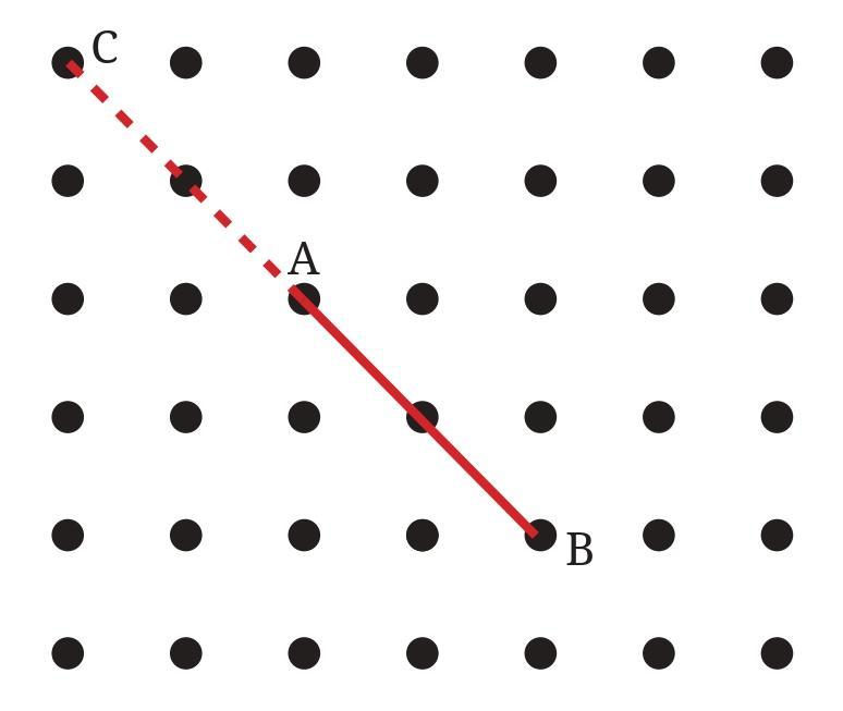
Answer:
A right angle measures $90^\circ$. To form a right angle at point A by joining A to other grid points, we need to draw two straight lines that pass through A and at least one other grid point in the figure, such that these two lines are perpendicular to each other at A.
Two lines are perpendicular if the product of their slopes is $-1$ (assuming neither line is vertical). If one line is vertical, the perpendicular line must be horizontal.
We need to identify all distinct pairs of lines passing through A and other grid points in the figure that have perpendicular slopes.
Let's consider point A as the origin $(0,0)$ of a coordinate system. The other grid points can be represented by integer coordinates $(x,y)$ relative to A.
A straight line joining A to a grid point $(x,y)$ has a slope given by $m = y/x$ (if $x \neq 0$). A vertical line has an undefined slope.
We examine the grid points visible in the figure relative to A and identify the possible slopes of lines passing through A and these points.
Possible slopes $m = y/x$ (or vertical):
1. Horizontal line: Passing through points like $(1,0), (-1,0)$, etc. Slope is $0$.
2. Vertical line: Passing through points like $(0,1), (0,-1)$, etc. Slope is $Undefined$.
3. Diagonal lines: Passing through points like $(x,y)$ where $x \neq 0, y \neq 0$. We list the unique slope magnitudes and signs based on the grid points available:
- Slope $\pm 1$ (e.g., A to $(1,1)$ or A to $(1,-1)$)
- Slope $\pm 2$, $\pm 1/2$ (e.g., A to $(1,2)$ or A to $(2,1)$)
- Slope $\pm 3$, $\pm 1/3$ (e.g., A to $(1,3)$ or A to $(3,1)$)
- Slope $\pm 4$, $\pm 1/4$ (e.g., A to $(1,4)$ NO, A to $(4,1)$ YES. Slope 4 is not possible with available grid points, but $1/4$ is.)
- Slope $\pm 3/2$, $\pm 2/3$ (e.g., A to $(2,3)$ or A to $(3,2)$)
- Slope $\pm 4/3$, $\pm 3/4$ (e.g., A to $(3,4)$ NO, A to $(4,3)$ YES. Slope $4/3$ is not possible, but $3/4$ is.)
Now we find pairs of slopes $(m_1, m_2)$ from the list above such that $m_1 \cdot m_2 = -1$ or one is $0$ and the other is $Undefined$. We must ensure that lines with both slopes pass through A and at least one other grid point shown in the figure.
The distinct pairs of perpendicular slopes corresponding to lines through A and other grid points are:
1. Slope $0$ (Horizontal) and $Undefined$ (Vertical).
2. Slope $1$ and Slope $-1$. (e.g., Line through A and $(1,1)$, and line through A and $(1,-1)$)
3. Slope $2$ and Slope $-1/2$. (e.g., Line through A and $(1,2)$, and line through A and $(2,-1)$)
4. Slope $1/2$ and Slope $-2$. (e.g., Line through A and $(2,1)$, and line through A and $(1,-2)$)
5. Slope $3$ and Slope $-1/3$. (e.g., Line through A and $(1,3)$, and line through A and $(3,-1)$)
6. Slope $1/3$ and Slope $-3$. (e.g., Line through A and $(3,1)$, and line through A and $(1,-3)$)
7. Slope $1/4$ and Slope $-4$. (e.g., Line through A and $(4,1)$, and line through A and $(1,-4)$)
8. Slope $3/4$ and Slope $-4/3$. (e.g., Line through A and $(4,3)$, and line through A and $(3,-4)$)
9. Slope $2/3$ and Slope $-3/2$. (e.g., Line through A and $(3,2)$, and line through A and $(2,-3)$)
Each of these pairs of slopes corresponds to a distinct pair of perpendicular lines passing through A and other grid points in the figure. These are the different ways to get a right angle at A by joining A to other grid points.
Therefore, there are 9 different ways of doing it.
(a) How many right angles do you have now? Justify why the angles are exact right angles.
(b) Describe how you folded the paper so that any other person who doesn’t know the process can simply follow your description to get the right angle.
Answer:
(a) How many right angles do you have now? Justify why the angles are exact right angles.
When a straight line (the second crease) intersects another straight line (the first slanting crease) such that they are perpendicular, they form four right angles at the point of intersection.
So, you will have 4 right angles formed where the two creases intersect.
Justification:
The angles are exact right angles because of the way the second crease is formed. When you fold the paper such that the first crease lies along itself (or one part of it lies exactly on the other part when folded along the second crease), and the fold line passes through the point you want the perpendicular at, the paper is essentially being folded along the line that bisects the straight angle ($180^\circ$) formed by the first crease at that point. Folding a straight angle in half like this creates two equal angles, and since a straight angle is $180^\circ$, each of the two equal angles is $180^\circ / 2 = 90^\circ$. Thus, the fold line (the second crease) is perpendicular to the first crease, resulting in exact right angles ($\boldsymbol{90^\circ}$).
(b) Describe how you folded the paper so that any other person who doesn’t know the process can simply follow your description to get the right angle.
Here is a description of the folding process:
Step 1: Get a slanting crease.
Take a sheet of paper.
Fold the paper anywhere across its surface. Make sure the fold is not perfectly horizontal or vertical. Make a firm crease. This is your first, slanting crease.
Unfold the paper. You will see the slanting crease.
Step 2: Get a crease perpendicular to the slanting crease.
Choose a point on the slanting crease where you want the right angle to be formed.
Now, fold the paper again, this time carefully aligning the paper so that the slanting crease lies exactly on top of itself.
While keeping the slanting crease perfectly aligned with itself, adjust the fold line such that it passes through the point you chose in the previous step.
Once the slanting crease is folded back onto itself and the fold line goes through the chosen point, press firmly to make the second crease.
Unfold the paper again.
You will now see two creases intersecting at the point you chose. The second crease is perpendicular to the first slanting crease, and they form four right angles at their intersection.
Figure it Out (Page 31 - 32)
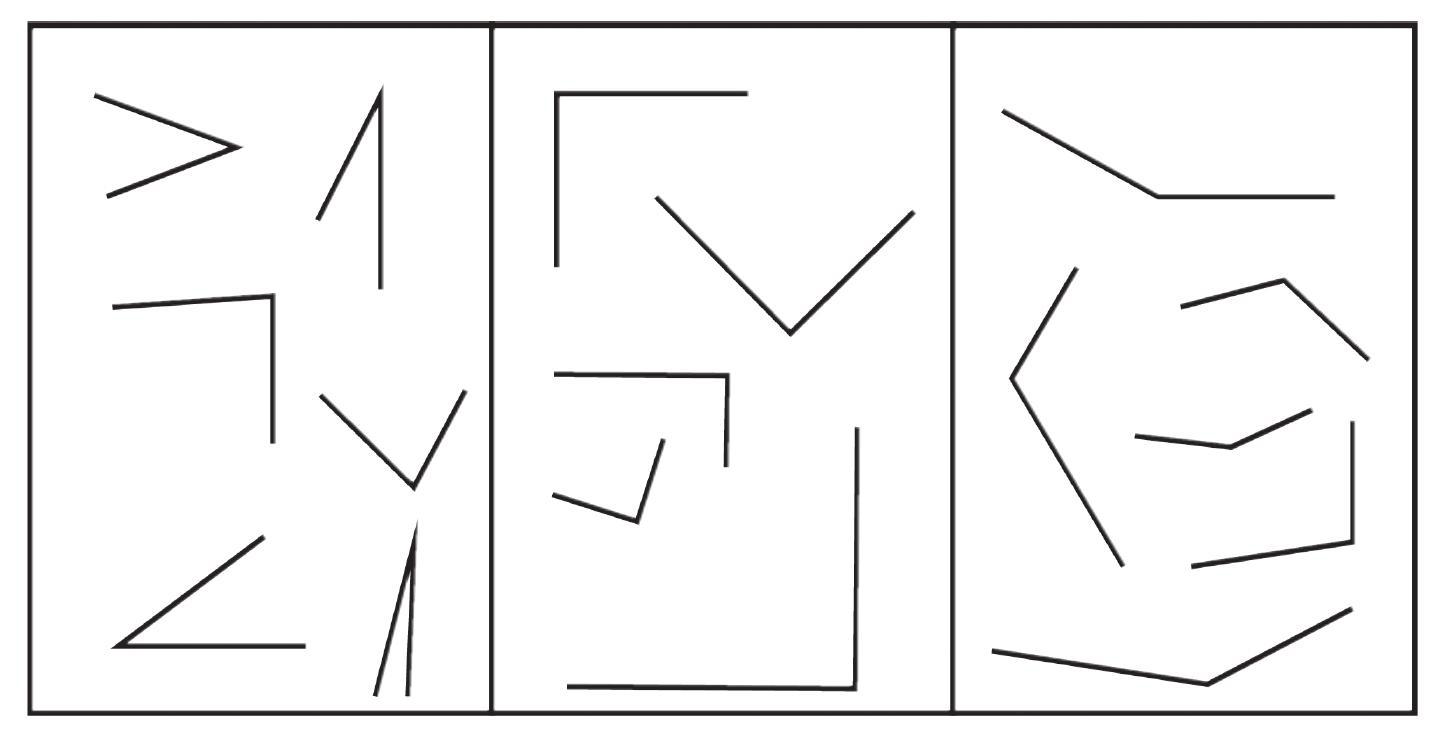
Question 1. Identify acute, right, obtuse and straight angles in the previous figures.
Answer:
Let's identify the different types of angles in the figures provided previously (from pages 29-31) and the current figure (from pages 31-32).
These figures mainly consist of grid points and lines drawn or implied on a grid.
1. Right Angles: ($\boldsymbol{90^\circ}$)
- The corners of the grid squares themselves form right angles.
- In the context of Question 1 (Figure it Out, Page 29), the corners of classroom windows are typically right angles.
- In the context of Question 3 (Figure it Out, Page 30-31), the pairs of perpendicular lines drawn through point A form right angles at A.
- The corners where horizontal and vertical grid lines intersect form right angles.
2. Straight Angles: ($\boldsymbol{180^\circ}$)
- Any straight line segment shown or implied on the grid forms a straight angle at any point along the line.
- In the context of Question 2 (Figure it Out, Page 30), the straight lines joining point A to other grid points form straight angles. A straight line itself can be considered as forming a straight angle.
- In the context of Question 4 (Figure it Out, Page 31), a straight crease on the paper represents a straight angle.
3. Acute Angles: (Greater than $0^\circ$ and less than $90^\circ$)
- Angles formed by the intersection of diagonal lines with horizontal or vertical lines on the grid.
- Angles formed between different diagonal lines passing through point A.
- For example, in the figures with point A, the angle formed by the horizontal line through A and a diagonal line like the one passing through A and $(1,1)$ (relative to A as $(0,0)$) is an acute angle ($45^\circ$). Similarly, lines to $(2,1)$, $(3,1)$, $(4,1)$, etc., form different acute angles with the horizontal.
4. Obtuse Angles: (Greater than $90^\circ$ and less than $180^\circ$)
- Angles formed by the intersection of diagonal lines with horizontal or vertical lines on the grid, specifically the angle that is greater than $90^\circ$ in such intersections.
- Angles formed between different diagonal lines passing through point A.
- For example, in the figures with point A, the angle formed by the horizontal line through A and a diagonal line like the one passing through A and $(1,1)$ also has an obtuse angle as its supplementary angle ($180^\circ - 45^\circ = 135^\circ$). Similarly, lines to $(2,1)$, $(3,1)$, $(4,1)$, etc., form different obtuse angles with the horizontal.
In essence, the grid structure allows for the visualization of all four types of angles depending on which lines (horizontal, vertical, or diagonal) are considered and how they intersect.
Question 2. Make a few acute angles and a few obtuse angles. Draw them in different orientations.
Answer:
To make or draw angles, you can use a ruler and a protractor, or you can draw them freehand, keeping in mind the definition of each type of angle.
An acute angle is an angle that measures less than $90^\circ$ but more than $0^\circ$.
An obtuse angle is an angle that measures greater than $90^\circ$ but less than $180^\circ$.
Here's how you can draw them and consider different orientations:
1. Drawing Acute Angles:
- Draw a point (vertex) and a straight line segment extending from it (one arm of the angle).
- From the same vertex, draw another straight line segment (the second arm).
- Ensure the opening between the two arms is smaller than the opening of a right angle ($90^\circ$).
- Draw examples like $30^\circ$, $45^\circ$, $60^\circ$, $75^\circ$ etc.
- Different Orientations: You can draw these acute angles with the vertex pointing up, down, left, or right, and the arms extending in various directions while maintaining the angle measure. For example, an acute angle can open upwards and to the right, downwards and to the left, etc.
2. Drawing Obtuse Angles:
- Draw a point (vertex) and a straight line segment extending from it (one arm).
- From the same vertex, draw another straight line segment (the second arm).
- Ensure the opening between the two arms is larger than the opening of a right angle ($90^\circ$) but smaller than a straight line ($180^\circ$).
- Draw examples like $100^\circ$, $120^\circ$, $135^\circ$, $150^\circ$ etc.
- Different Orientations: Similar to acute angles, obtuse angles can be drawn with the vertex and arms pointing in many different directions. An obtuse angle can open downwards and to the right, upwards and to the left, etc.
Imagine drawing an 'L' shape for a right angle. An acute angle will have a smaller opening than the 'L', and an obtuse angle will have a wider opening than the 'L' but not flat like a straight line.
Using a protractor helps in drawing angles of specific measures accurately. Without a protractor, you can compare against an approximate right angle (like the corner of a book) to guide your drawing of acute and obtuse angles.
Question 3. Do you know what the words acute and obtuse mean? Acute means sharp and obtuse means blunt. Why do you think these words have been chosen?
Answer:
Yes, the common meanings of the words are indeed "acute" meaning sharp and "obtuse" meaning blunt.
These words were likely chosen to describe angles based on their visual appearance or "pointiness" compared to a right angle.
1. Acute Angles ($\boldsymbol{< 90^\circ}$): An angle less than $90^\circ$ looks sharp or pointed. Think of the tip of a needle, a sharp knife, or the corner of a pointed object. These objects have angles that are typically acute. The smaller the angle, the sharper the point appears. This aligns perfectly with the meaning of "acute" as sharp.
2. Obtuse Angles ($\boldsymbol{> 90^\circ}$ and $\boldsymbol{< 180^\circ}$): An angle greater than $90^\circ$ looks wider, less pointed, or "blunt". Think of the end of a blunt pencil or a blunt instrument. The point is not sharp. The wider the angle (closer to $180^\circ$), the more blunt it appears. This corresponds well with the meaning of "obtuse" as blunt or not sharp.
So, the terms acute and obtuse are descriptive names that relate the geometric property of the angle's measure to the everyday visual concept of sharpness or bluntness.

What will be the next figure and how many acute angles will it have? Do you notice any pattern in the numbers?
Answer:
Let's analyze each figure to count the number of acute angles.
Figure 1: This figure shows two rays originating from a point, forming one angle. Visually, this angle is less than $90^\circ$.
Number of acute angles in Figure 1 = 1.
Figure 2: This figure shows three rays originating from a point, forming two adjacent angles. Visually, both of these angles are less than $90^\circ$.
Number of acute angles in Figure 2 = 2.
Figure 3: This figure shows four rays originating from a point, forming three adjacent angles. Visually, all three of these angles are less than $90^\circ$.
Number of acute angles in Figure 3 = 3.
Based on the pattern observed in the first three figures (1, 2, 3 acute angles), the next figure will likely follow the same rule of adding one more ray and thus one more acute angle.
The next figure in the sequence would consist of five rays originating from a central point, creating four adjacent angles.
Based on the pattern, the number of acute angles in the next figure will be 4.
The pattern in the number of acute angles is that it increases by 1 in each successive figure. If we consider the figure number starting from 1, the number of acute angles in Figure $n$ is $n$. Alternatively, if we count the number of rays in each figure (2, 3, 4, ...), the number of acute angles is one less than the number of rays.
Intext Question (Page 34)
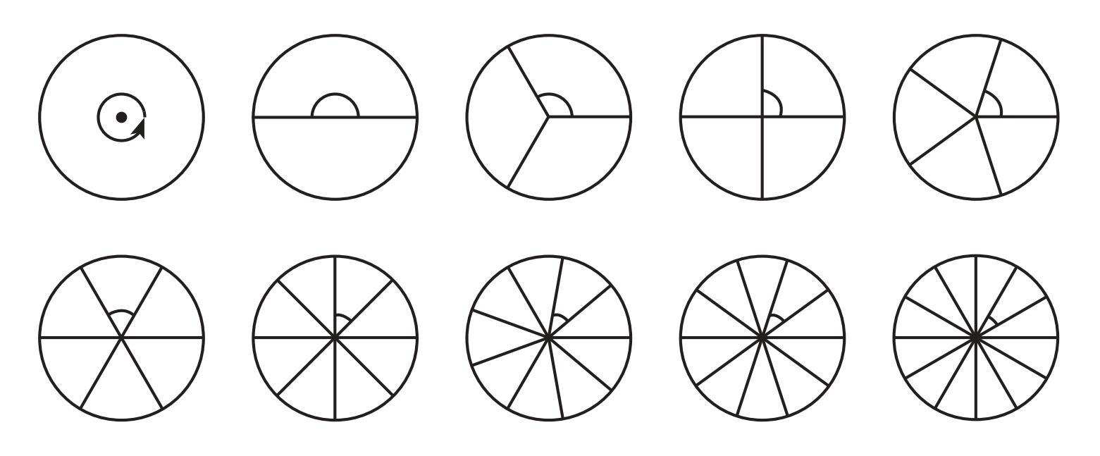
Answer:
The total angle around the center of a circle is $360^\circ$.
When a circle is divided into $n$ equal parts, the measure of each resulting angle at the center is found by dividing the total angle by the number of parts.
Measure of each angle = $\frac{360^\circ}{\text{Number of parts}}$
Let's calculate the degree measure for each case:
1. Circle divided into 1 part:
Angle = $\frac{360^\circ}{1} = 360^\circ$. This is a full angle.
2. Circle divided into 2 parts:
Angle = $\frac{360^\circ}{2} = 180^\circ$. This is a straight angle.
3. Circle divided into 3 parts:
Angle = $\frac{360^\circ}{3} = 120^\circ$. This is an obtuse angle.
4. Circle divided into 4 parts:
Angle = $\frac{360^\circ}{4} = 90^\circ$. This is a right angle.
5. Circle divided into 5 parts:
Angle = $\frac{360^\circ}{5} = 72^\circ$. This is an acute angle.
6. Circle divided into 6 parts:
Angle = $\frac{360^\circ}{6} = 60^\circ$. This is an acute angle.
7. Circle divided into 8 parts:
Angle = $\frac{360^\circ}{8} = 45^\circ$. This is an acute angle.
8. Circle divided into 9 parts:
Angle = $\frac{360^\circ}{9} = 40^\circ$. This is an acute angle.
9. Circle divided into 10 parts:
Angle = $\frac{360^\circ}{10} = 36^\circ$. This is an acute angle.
10. Circle divided into 12 parts:
Angle = $\frac{360^\circ}{12} = 30^\circ$. This is an acute angle.
Summary of degree measures:
- 1 part: $360^\circ$
- 2 parts: $180^\circ$
- 3 parts: $120^\circ$
- 4 parts: $90^\circ$
- 5 parts: $72^\circ$
- 6 parts: $60^\circ$
- 8 parts: $45^\circ$
- 9 parts: $40^\circ$
- 10 parts: $36^\circ$
- 12 parts: $30^\circ$
Figure it out (Page 35)
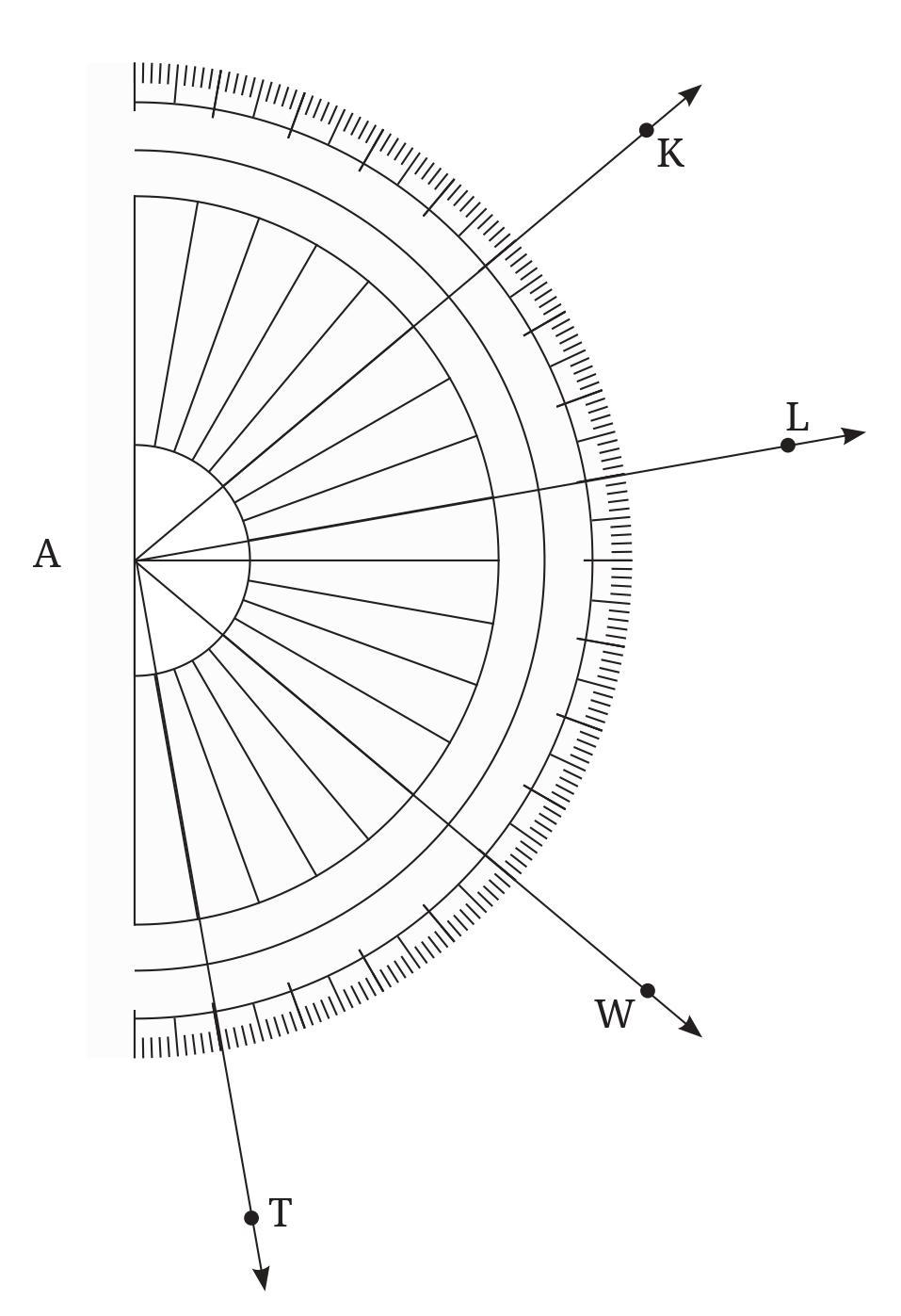
a. ∠ KAL
Notice that the vertex of this angle coincides with the centre of the protractor. So the number of units of 1 degree angle between KA and AL gives the measure of ∠KAL. By counting, we get
∠KAL = 30°.
Making use of the medium sized and large sized marks, is it possible to count the number of units in 5s or 10s?
b. ∠WAL
c. ∠TAK
Answer:
The angles are measured using the protractor shown in the figure, with the vertex at point A.
a. $\angle$ KAL
As noted in the question, the ray AK aligns with the $0^\circ$ mark and the ray AL aligns with the $30^\circ$ mark on the protractor. The measure of the angle is the difference between these readings.
Measure of $\angle$ KAL = Reading at AL - Reading at AK
Measure of $\angle$ KAL = $30^\circ - 0^\circ = 30^\circ$.
So, $\angle$KAL = $30^\circ$.
Regarding counting using the medium and large-sized marks:
Yes, it is possible to count in 5s and 10s using the medium and large-sized marks on the protractor.
The large marks are usually numbered ($0, 10, 20, 30, ...$) and represent multiples of $10^\circ$.
The medium marks are typically halfway between the large marks (e.g., at $5^\circ, 15^\circ, 25^\circ, ...$) and represent multiples of $5^\circ$.
By starting from the $0^\circ$ mark (along AK) and counting the $10^\circ$ intervals (large marks) and $5^\circ$ intervals (medium marks) up to the line AL, we can confirm the angle measure is $30^\circ$ ($10+10+10$ or $5+5+5+5+5+5$).
b. $\angle$ WAL
The ray AW aligns with the $60^\circ$ mark on the protractor.
The ray AL aligns with the $30^\circ$ mark on the protractor.
Measure of $\angle$ WAL = $|$Reading at AW - Reading at AL$|$
Measure of $\angle$ WAL = $|60^\circ - 30^\circ| = 30^\circ$.
So, $\angle$WAL = $30^\circ$.
c. $\angle$ TAK
The ray AT aligns with the $90^\circ$ mark on the protractor.
The ray AK aligns with the $0^\circ$ mark on the protractor.
Measure of $\angle$ TAK = $|$Reading at AT - Reading at AK$|$
Measure of $\angle$ TAK = $|90^\circ - 0^\circ| = 90^\circ$.
So, $\angle$TAK = $90^\circ$.
Intext Question (Page 36)
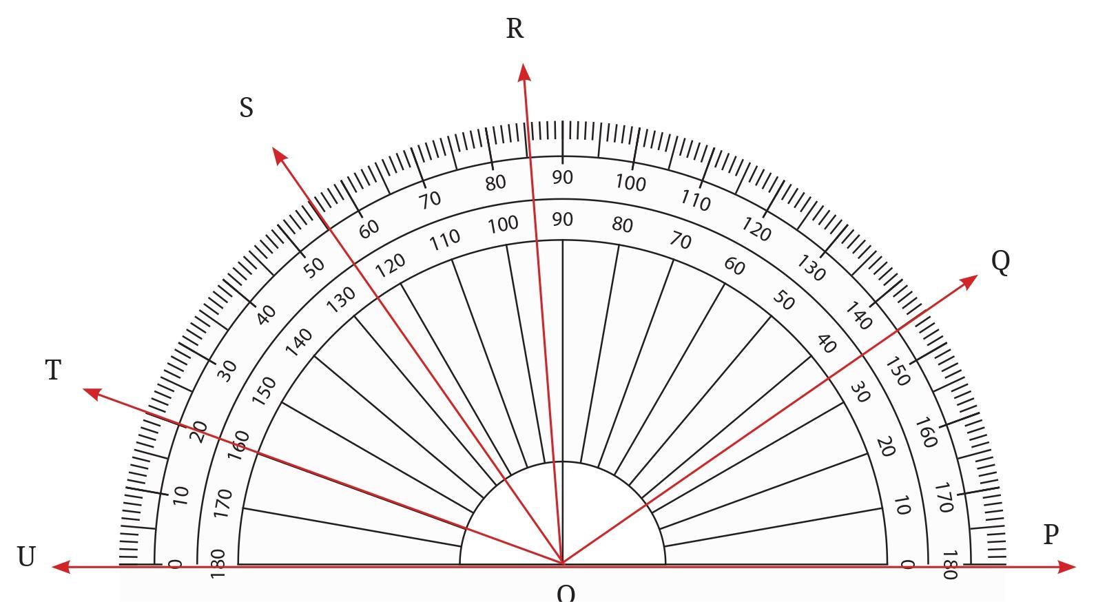
Answer:
The figure shows several rays originating from a common vertex (let's assume it is point O, the center of the protractor). The rays pass through points labeled A, B, C, D, E, F, and G on the protractor scale.
We can determine the measure of each angle formed by any two rays by reading the values on the protractor scale where the rays pass. Assuming the ray OA aligns with the $0^\circ$ mark, we read the following measures:
Ray OA: $0^\circ$
Ray OB: $30^\circ$
Ray OC: $60^\circ$
Ray OD: $90^\circ$
Ray OE: $120^\circ$
Ray OF: $150^\circ$
Ray OG: $180^\circ$
The angles are formed by pairs of these rays. We calculate the measure of each angle by finding the absolute difference between the scale readings of the two rays forming the angle.
Listing the different angles and their measures:
$\angle$AOB = $|30^\circ - 0^\circ| = 30^\circ$
$\angle$AOC = $|60^\circ - 0^\circ| = 60^\circ$
$\angle$AOD = $|90^\circ - 0^\circ| = 90^\circ$
$\angle$AOE = $|120^\circ - 0^\circ| = 120^\circ$
$\angle$AOF = $|150^\circ - 0^\circ| = 150^\circ$
$\angle$AOG = $|180^\circ - 0^\circ| = 180^\circ$
$\angle$BOC = $|60^\circ - 30^\circ| = 30^\circ$
$\angle$BOD = $|90^\circ - 30^\circ| = 60^\circ$
$\angle$BOE = $|120^\circ - 30^\circ| = 90^\circ$
$\angle$BOF = $|150^\circ - 30^\circ| = 120^\circ$
$\angle$BOG = $|180^\circ - 30^\circ| = 150^\circ$
$\angle$COD = $|90^\circ - 60^\circ| = 30^\circ$
$\angle$COE = $|120^\circ - 60^\circ| = 60^\circ$
$\angle$COF = $|150^\circ - 60^\circ| = 90^\circ$
$\angle$COG = $|180^\circ - 60^\circ| = 120^\circ$
$\angle$DOE = $|120^\circ - 90^\circ| = 30^\circ$
$\angle$DOF = $|150^\circ - 90^\circ| = 60^\circ$
$\angle$DOG = $|180^\circ - 90^\circ| = 90^\circ$
$\angle$EOF = $|150^\circ - 120^\circ| = 30^\circ$
$\angle$EOG = $|180^\circ - 120^\circ| = 60^\circ$
$\angle$FOG = $|180^\circ - 150^\circ| = 30^\circ$
Intext Question (Page 39 - 40)

Question:
Think !
In Fig. 2.20, we have ∠AOB = ∠BOC = ∠COD = ∠DOE = ∠EOF = ∠FOG = ∠GOH = ∠HOI=_____. Why?
Answer:
The question states that in Figure 2.20, the angles formed by consecutive rays from the center are equal: $\angle$AOB = $\angle$BOC = $\angle$COD = $\angle$DOE = $\angle$EOF = $\angle$FOG = $\angle$GOH = $\angle$HOI.
The reason for their equality is that the semicircle arc from A to I is divided into equal parts by the points B, C, D, E, F, G, H.
The total angle subtended by a semicircle at its center is a straight angle, which measures $180^\circ$. The points A, B, C, D, E, F, G, H, I divide this $180^\circ$ angle into several smaller, equal angles.
Let's count the number of equal angles formed. The points A to I define segments AB, BC, CD, DE, EF, FG, GH, HI along the arc. There are 8 such segments. Each segment corresponds to one angle at the center formed by consecutive rays (OA and OB, OB and OC, etc.). Thus, there are 8 equal angles: $\angle$AOB, $\angle$BOC, $\angle$COD, $\angle$DOE, $\angle$EOF, $\angle$FOG, $\angle$GOH, $\angle$HOI.
Since the sum of these 8 equal angles is $180^\circ$ (the straight angle $\angle$AOI), the measure of each angle can be calculated by dividing $180^\circ$ by the number of equal angles (which is 8).
Measure of each angle = $\frac{\text{Total angle}}{\text{Number of equal parts}}$
Measure of each angle = $\frac{180^\circ}{8}$
$\frac{180}{8} = \frac{90}{4} = \frac{45}{2} = 22.5$
Measure of each angle = $22.5^\circ$
So, $\angle$AOB = $\angle$BOC = $\angle$COD = $\angle$DOE = $\angle$EOF = $\angle$FOG = $\angle$GOH = $\angle$HOI = $22.5^\circ$.
The reason they are equal is precisely because the points B, C, D, E, F, G, H divide the semicircle arc AI into 8 equal parts, and angles at the center subtended by equal arcs are equal.
Figure it Out (Page 40 - 43)
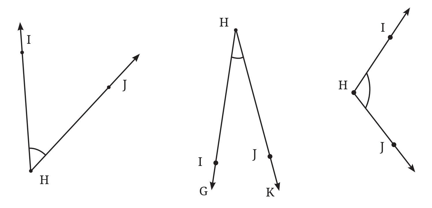
Answer:
To find the degree measures of the angles, you need to use a protractor. Place the vertex of the angle at the center of the protractor's base line and align one arm of the angle with the $0^\circ$ mark. Then, read the measure on the protractor scale where the other arm of the angle passes.
Based on visual inspection of the figure and using a protractor (as instructed):
The angle marked with the red arc appears to be an obtuse angle. Using a protractor, its measure is approximately $120^\circ$.
The angle marked with the blue arc appears to be an acute angle. Using a protractor, its measure is approximately $60^\circ$.
The angle marked with the green arc appears to be a right angle. Using a protractor, its measure is exactly $90^\circ$.
The angle marked with the purple arc appears to be a large obtuse angle. Using a protractor, its measure is approximately $150^\circ$.
Therefore, the approximate measures of the angles are:
Angle with red arc: $120^\circ$
Angle with blue arc: $60^\circ$
Angle with green arc: $90^\circ$
Angle with purple arc: $150^\circ$
Answer:
To find the degree measures of different angles in your classroom using a protractor, you need to identify corners or intersections of lines (like edges of objects, lines drawn on the board, etc.) that form angles.
Here's the general procedure for measuring an angle using a protractor:
1. Identify the vertex of the angle you want to measure.
2. Place the center point of the protractor exactly on the vertex of the angle.
3. Align the baseline of the protractor along one arm of the angle, making sure the $0^\circ$ mark is on that arm.
4. Read the measure on the protractor scale where the other arm of the angle crosses the curved edge of the protractor. Use the scale that starts from $0^\circ$ along the first arm.
Here are some places in a typical classroom where you can find angles to measure:
1. Corners of Walls, Floor, and Ceiling: Where two walls meet, where a wall meets the floor, or where a wall meets the ceiling. These are usually designed to be right angles ($90^\circ$).
2. Corners of Desks, Tables, Chairs, Cupboards, Whiteboard/Blackboard, Doors, Windows: The corners of rectangular or square objects are typically right angles ($90^\circ$).
3. Angles of a Triangular Ruler (Set Square): A standard set square often has angles of $90^\circ, 45^\circ,$ and $45^\circ$ (isosceles right triangle) or $90^\circ, 30^\circ,$ and $60^\circ$ (30-60-90 triangle). These are right and acute angles.
4. Angles formed by hands of a clock: If there is a clock in the classroom, the hands form different angles at different times. You can measure these angles (e.g., at 3:00 it's $90^\circ$, at 1:00 it's $30^\circ$, at 2:00 it's $60^\circ$, at 4:00 it's $120^\circ$, etc.). These can be acute, right, or obtuse angles.
5. Angles formed by slopes: If there's a ramp or a slanting surface, the angle it makes with the floor is an angle you can measure. This could be an acute angle.
6. Angles in diagrams or drawings on the board: Any angles drawn on the board can be measured if they are accessible and large enough.
Example Measurements (Likely Values):
- Corner of a door: Approximately $90^\circ$ (Right Angle)
- Corner of a desk: Approximately $90^\circ$ (Right Angle)
- Angle of a $45^\circ$ set square: $45^\circ$ (Acute Angle)
- Angle of a $60^\circ$ set square: $60^\circ$ (Acute Angle)
- Angle of a $30^\circ$ set square: $30^\circ$ (Acute Angle)
- Angle between the hour and minute hand at 4:00: $120^\circ$ (Obtuse Angle)
You should choose several different angles from the objects listed above and use your protractor to find their actual measures in your specific classroom.
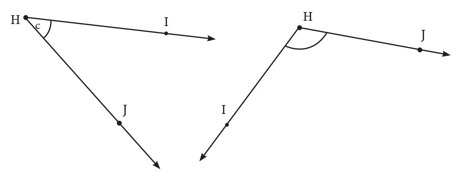
Answer:
To find the exact degree measures of these angles, you need to use your physical protractor. Align the vertex of the angle with the center of the protractor and one arm with the $0^\circ$ line, then read the measurement where the other arm crosses the protractor scale.
Based on visual inspection and using a protractor (as instructed):
1. $\angle$PQR: Place the protractor's center on vertex Q. Align arm QR with the $0^\circ$ mark (using the outer or inner scale). Read the degree measure where arm QP crosses the scale. Visually, this angle is obtuse, greater than $90^\circ$. Using a protractor, its measure is approximately $130^\circ$.
2. $\angle$LMN: Place the protractor's center on vertex M. Align arm MN with the $0^\circ$ mark. Read the degree measure where arm ML crosses the scale. Visually, this angle is obtuse, greater than $90^\circ$. Using a protractor, its measure is approximately $110^\circ$.
3. Angle at vertex C: This angle is part of the polygon shown. Place the protractor's center on vertex C. Align one arm (say, the horizontal one extending to the right from C) with the $0^\circ$ mark. Read the measure where the other arm (extending upwards and right from C) crosses the scale. Visually, this angle is acute, less than $90^\circ$. Using a protractor, its measure is approximately $45^\circ$.
Check if your paper protractor can be used here:
Yes, a standard paper protractor (which typically measures angles up to $180^\circ$) can be used to measure all the angles shown in the figure.
The angles $\angle$PQR, $\angle$LMN, and the angle at C are all angles less than $180^\circ$. A standard $180^\circ$ protractor is designed to measure angles in this range.
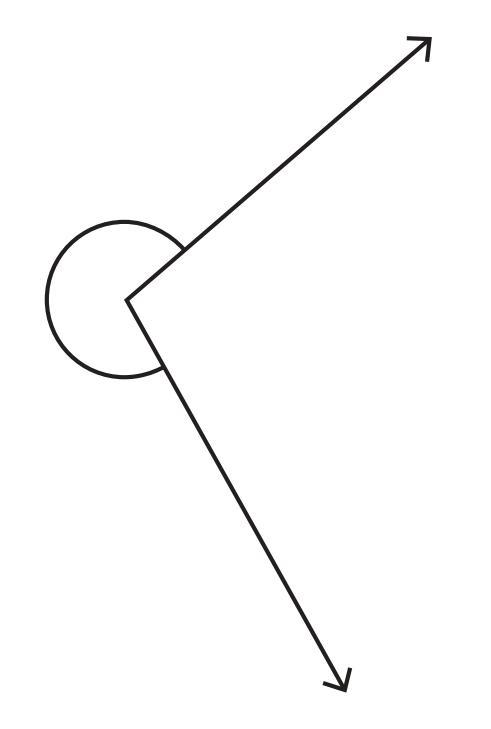
Answer:
The angle shown in the figure is a reflex angle. A reflex angle is an angle whose measure is greater than $180^\circ$ but less than $360^\circ$.
A standard protractor is usually a semicircle and measures angles up to $180^\circ$. Therefore, we cannot directly measure a reflex angle using a standard $180^\circ$ protractor.
However, we can find the measure of the reflex angle by measuring the corresponding non-reflex angle (the smaller angle formed by the same two arms) and subtracting that measure from the total angle around a point ($360^\circ$).
Here are the steps to find the degree measure of the given reflex angle using a standard $180^\circ$ protractor:
1. Identify the vertex of the angle (the point where the two rays meet). Let's call the vertex V.
2. Identify the two arms of the angle (the two rays originating from V). Let's call the arms VR and VS.
3. Notice that the arms VR and VS form two angles: the marked reflex angle (greater than $180^\circ$) and a smaller, unmarked angle (less than $180^\circ$).
4. Use the protractor to measure the smaller angle formed by the arms VR and VS. Place the center of the protractor on the vertex V and align the baseline with one arm (say, VR) such that the $0^\circ$ mark is on VR. Read the measure where the other arm (VS) crosses the protractor scale. Let this measure be $x^\circ$.
For example, if the smaller angle measures $100^\circ$, then $x = 100$.
5. The total angle around the vertex V is $360^\circ$. The reflex angle is the remaining part of the circle after the smaller angle is removed.
Reflex angle measure = Total angle around a point - Measure of the smaller angle
Reflex angle measure = $360^\circ - x^\circ$
If, for example, the smaller angle measured $100^\circ$, then the reflex angle measure would be $360^\circ - 100^\circ = 260^\circ$.
Therefore, to find the degree measure of the given reflex angle, you measure the inner angle using your protractor and subtract that value from $360^\circ$.

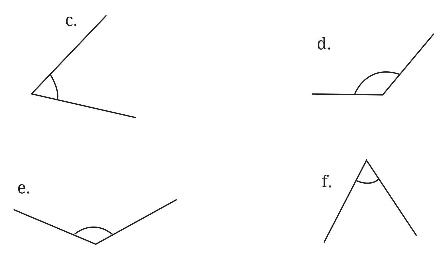
Answer:
To accurately find the degree measure of each angle, you need to use a protractor. Follow these steps for each angle:
1. Place the center of the protractor exactly on the vertex of the angle.
2. Align the base line of the protractor with one arm of the angle, making sure the $0^\circ$ mark on the protractor's scale lies along this arm.
3. Read the measure on the protractor scale where the other arm of the angle crosses the curved edge of the protractor. Use the scale that starts from $0^\circ$ along the first aligned arm.
Based on visual inspection of the figures, here are the approximate measures. You should use your protractor for precise measurements:
First Figure (Angles on Grid):
- Top-left angle: This appears to be a right angle. Using a protractor, its measure is $90^\circ$.
- Top-right angle: This angle is formed by a horizontal line and a line going diagonally down and right. Based on the grid, it looks like it goes across 2 units horizontally and 2 units vertically (or similar proportion). This suggests an angle of 45 degrees with the horizontal/vertical. The angle shown with the arc is the larger angle, likely obtuse. Measure the acute angle ($45^\circ$) and subtract from $180^\circ$. $180^\circ - 45^\circ = 135^\circ$. Using a protractor, its measure is approximately $135^\circ$.
- Bottom-left angle: This angle is formed by a vertical line and a line going diagonally up and right. Based on the grid, it looks like it goes 2 units vertically and 2 units horizontally. This suggests an angle of 45 degrees with the vertical/horizontal. The angle shown is acute. Using a protractor, its measure is approximately $45^\circ$.
- Bottom-right angle: This appears to be an angle formed by a horizontal line and a line going diagonally up and left. Based on the grid, it looks like it goes 2 units horizontally and 2 units vertically. This suggests an angle of 45 degrees with the horizontal/vertical. The angle shown is acute. Using a protractor, its measure is approximately $45^\circ$.
Second Figure (Angles in Shapes):
- Top angle in the triangle: This angle appears to be acute. Using a protractor, its measure is approximately $70^\circ$.
- Bottom-left angle in the triangle: This angle appears to be acute. Using a protractor, its measure is approximately $60^\circ$.
- Bottom-right angle in the triangle: This angle appears to be acute. Using a protractor, its measure is approximately $50^\circ$.
(Note: The sum of angles in a triangle should be $180^\circ$. $70^\circ + 60^\circ + 50^\circ = 180^\circ$, which suggests these approximations are reasonable.)
- Top-left angle in the quadrilateral: This angle appears to be obtuse. Using a protractor, its measure is approximately $110^\circ$.
- Top-right angle in the quadrilateral: This angle appears to be acute. Using a protractor, its measure is approximately $80^\circ$.
- Bottom-right angle in the quadrilateral: This angle appears to be obtuse. Using a protractor, its measure is approximately $100^\circ$.
- Bottom-left angle in the quadrilateral: This angle appears to be acute. Using a protractor, its measure is approximately $70^\circ$.
(Note: The sum of angles in a quadrilateral should be $360^\circ$. $110^\circ + 80^\circ + 100^\circ + 70^\circ = 360^\circ$, which suggests these approximations are reasonable.)
Please use your physical protractor to get the exact measurements for the angles in the figure.
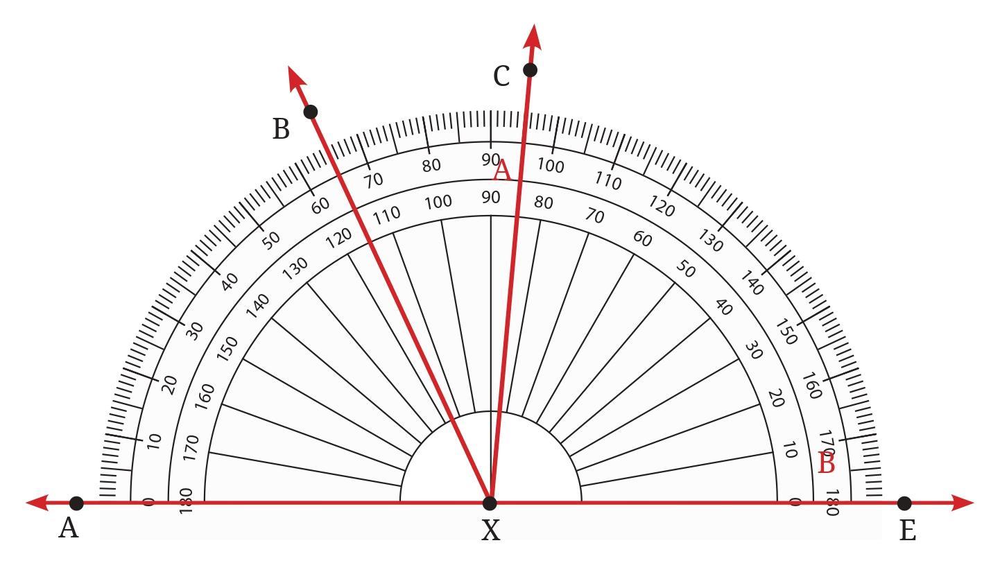
Answer:
The angles are measured using the protractor shown in the figure, with the vertex at point X. We need to read the degree values corresponding to the points on the protractor scale where the rays pass through.
Assuming we use the lower scale of the protractor (starting from $0^\circ$ on the left), the readings for the relevant rays are:
Ray XA: $0^\circ$
Ray XB: $40^\circ$
Ray XC: $90^\circ$
Ray XE: $140^\circ$
Now, we calculate the measure of each angle by finding the absolute difference between the scale readings of the two rays forming the angle.
1. $\angle$ BXE: This angle is formed by rays XB and XE.
Measure of $\angle$ BXE = $|$Reading at XE - Reading at XB$|$
Measure of $\angle$ BXE = $|140^\circ - 40^\circ| = 100^\circ$
So, $\angle$BXE = $100^\circ$.
2. $\angle$ CXE: This angle is formed by rays XC and XE.
Measure of $\angle$ CXE = $|$Reading at XE - Reading at XC$|$
Measure of $\angle$ CXE = $|140^\circ - 90^\circ| = 50^\circ$
So, $\angle$CXE = $50^\circ$.
3. $\angle$ AXB: This angle is formed by rays XA and XB.
Measure of $\angle$ AXB = $|$Reading at XB - Reading at XA$|$
Measure of $\angle$ AXB = $|40^\circ - 0^\circ| = 40^\circ$
So, $\angle$AXB = $40^\circ$.
4. $\angle$ BXC: This angle is formed by rays XB and XC.
Measure of $\angle$ BXC = $|$Reading at XC - Reading at XB$|$
Measure of $\angle$ BXC = $|90^\circ - 40^\circ| = 50^\circ$
So, $\angle$BXC = $50^\circ$.
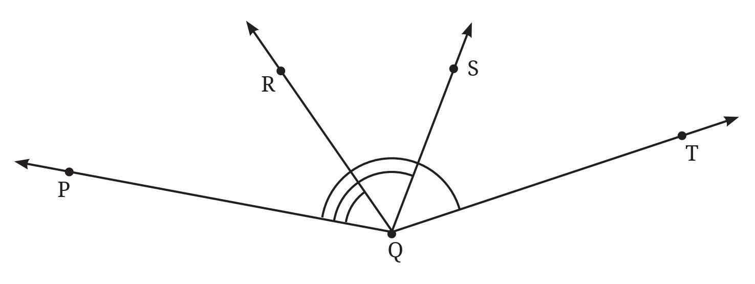
Answer:
The angles are measured using the protractor shown in the figure, with the vertex at point P. We need to read the degree values corresponding to the points on the protractor scale where the rays pass through. Assume the ray PT aligns with the $0^\circ$ mark.
Based on the protractor scale in the figure, the readings for the relevant rays are:
Ray PT: $0^\circ$
Ray PQ: $40^\circ$
Ray PS: $90^\circ$
Ray PR: $130^\circ$
Now, we calculate the measure of each angle by finding the absolute difference between the scale readings of the two rays forming the angle.
1. $\angle$ PQR: This angle is formed by rays PQ and PR, with vertex P.
Measure of $\angle$ PQR = $|$Reading at PR - Reading at PQ$|$
Measure of $\angle$ PQR = $|130^\circ - 40^\circ| = 90^\circ$
So, $\angle$PQR = $90^\circ$.
2. $\angle$ PQS: This angle is formed by rays PQ and PS, with vertex P.
Measure of $\angle$ PQS = $|$Reading at PS - Reading at PQ$|$
Measure of $\angle$ PQS = $|90^\circ - 40^\circ| = 50^\circ$
So, $\angle$PQS = $50^\circ$.
3. $\angle$ PQT: This angle is formed by rays PQ and PT, with vertex P.
Measure of $\angle$ PQT = $|$Reading at PQ - Reading at PT$|$
Measure of $\angle$ PQT = $|40^\circ - 0^\circ| = 40^\circ$
So, $\angle$PQT = $40^\circ$.
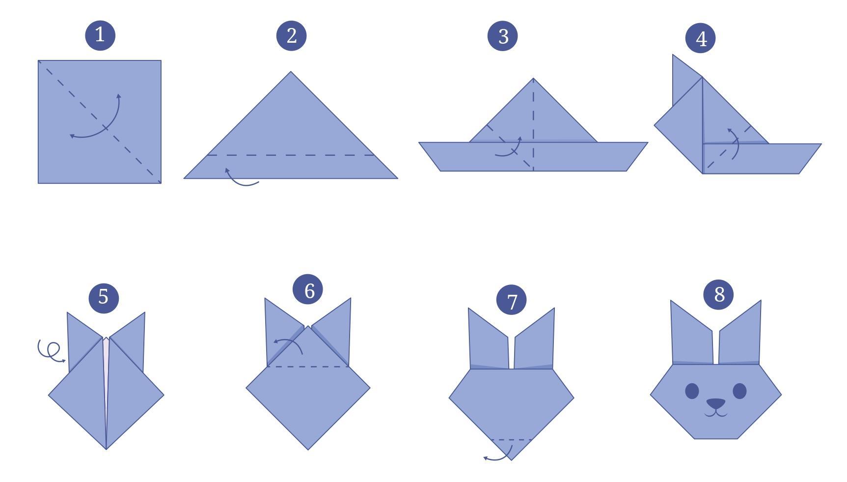
Answer:
This question involves a paper folding activity followed by measurement. As I cannot physically perform the folding, I will describe the steps based on the figures and explain what you should do and what results you are likely to get.
Instructions to make the paper craft:
1. Take a rectangular sheet of paper. Identify one corner, let's call it A (like the top-left corner in the image).
2. Fold corner A down onto the opposite edge (the bottom edge of the paper). Adjust the position of A on the bottom edge and the position of the fold line until you are satisfied. Make a firm crease.
3. Unfold the paper. You will see the first crease.
4. Fold the paper again. This time, carefully align the first crease onto itself. As you make this new fold, ensure that the fold line passes through the original position of corner A (the corner you started with). Make a firm crease.
5. Unfold the paper. You now have two creases. These two creases are perpendicular to each other and intersect at the original position of corner A.
6. Perform the third fold as shown in Image 5. This step involves folding a part of the paper such that a previously made crease or edge aligns with another crease or point. (The exact alignment is not perfectly clear from the image alone, but it's likely a fold designed to divide angles or lines created in the previous steps).
7. Make a firm crease for the third fold.
8. Unfold the paper completely.
Drawing lines on the creases and measuring angles:
1. Using a ruler and a pencil, carefully draw a line exactly on top of each crease made during the folding process.
2. You will notice that several of these lines intersect at a central point (which should be related to the original position of corner A or the folds made). These intersecting lines form several angles around this central point.
3. Use your protractor to measure the degree of each angle formed between adjacent lines around the central intersection point.
Expected result and pattern:
Based on the final figure (Image 8) provided in the question, the creases form lines that divide the full angle around the central point ($360^\circ$) into several angles. Visually, the figure shows lines that suggest 8 angles around the center.
If the folding process results in 8 equally spaced lines (like spokes on a wheel), they would divide the $360^\circ$ into 8 equal angles.
Measure of each angle = $\frac{360^\circ}{\text{Number of equal divisions}}$
Assuming 8 equal angles based on the figure:
Measure of each angle = $\frac{360^\circ}{8} = 45^\circ$
Therefore, after performing the folding, drawing the lines, and measuring the angles with your protractor, you are likely to find that the angles formed between adjacent lines are approximately $45^\circ$. You might also find angles which are sums of these basic angles, such as $90^\circ$ (formed by two adjacent $45^\circ$ angles), $135^\circ$ (sum of three $45^\circ$ angles), etc.
Try it for other triangles as well, and then make a conjecture for what happens in general! We will come back to why this happens in a later year.
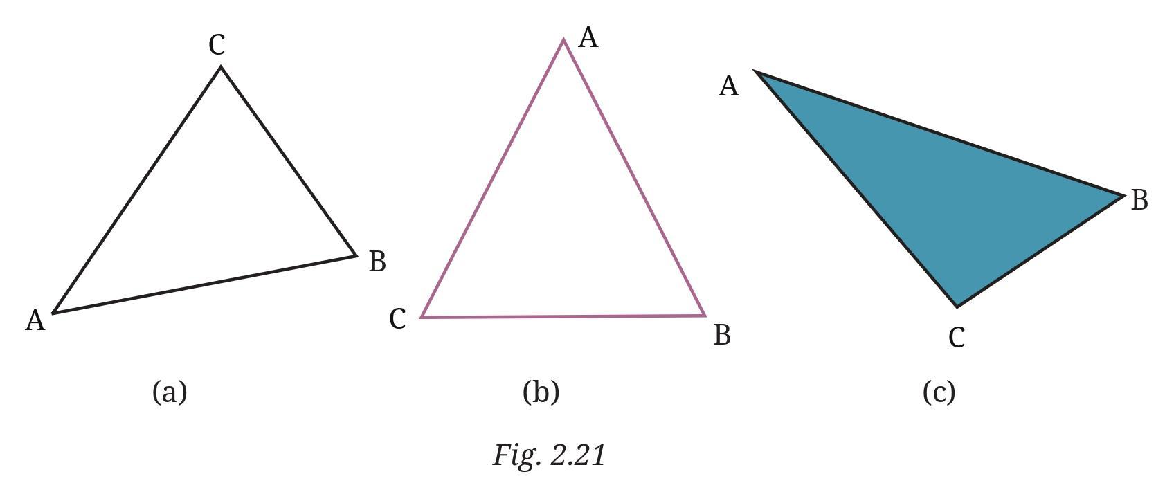
Answer:
To find the degree measures of the angles in each triangle, you need to use a protractor. Follow these steps for each triangle:
1. For each angle of the triangle, place the center point of your protractor exactly on the vertex of the angle.
2. Align the base line of the protractor along one side (arm) of the angle, making sure the $0^\circ$ mark on the protractor's scale lies along this side.
3. Read the measure on the protractor scale where the other side (arm) of the angle crosses the curved edge of the protractor. Use the scale that starts from $0^\circ$ along the first aligned side.
4. Write down the measured degree measure near the respective angle in the figure.
5. After measuring all three angles of a triangle, add the three measured values together.
Based on measuring the angles from the provided figure using a protractor:
Figure 2.21 (a): Triangle 1
Let the vertices of the triangle be A, B, and C.
Measure of $\angle$A $\approx 60^\circ$
Measure of $\angle$B $\approx 70^\circ$
Measure of $\angle$C $\approx 50^\circ$
Sum of angles = $60^\circ + 70^\circ + 50^\circ = 180^\circ$
Figure 2.21 (b): Triangle 2
Let the vertices of the triangle be P, Q, and R.
Measure of $\angle$P $\approx 40^\circ$
Measure of $\angle$Q $\approx 110^\circ$
Measure of $\angle$R $\approx 30^\circ$
Sum of angles = $40^\circ + 110^\circ + 30^\circ = 180^\circ$
Figure 2.21 (c): Triangle 3
Let the vertices of the triangle be X, Y, and Z.
Measure of $\angle$X $\approx 30^\circ$
Measure of $\angle$Y $\approx 90^\circ$
Measure of $\angle$Z $\approx 60^\circ$
Sum of angles = $30^\circ + 90^\circ + 60^\circ = 180^\circ$
In all three triangles, the sum of the measures of the three angles is $180^\circ$. You are likely to get sums very close to $180^\circ$ when using your physical protractor (minor differences might occur due to measurement accuracy).
Conjecture:
Based on the measurements of these triangles and trying it for other triangles (of different shapes and sizes), the sum of the three angles in any triangle appears to be constant, equal to $180^\circ$.
Therefore, the conjecture is: The sum of the interior angles of any triangle is always $180^\circ$.
Figure it Out (Page 45 - 46)
a. The hands of a clock make different angles at different times. At 1 o’clock, the angle between the hands is 30°. Why?
b. What will be the angle at 2 o’clock? And at 4 o’clock? 6 o’clock?
c. Explore other angles made by the hands of a clock.
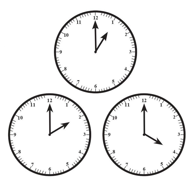
Answer:
a. The hands of a clock make different angles at different times. At 1 o’clock, the angle between the hands is 30°. Why?
A clock face is a circle, which represents a total angle of $360^\circ$ around the center.
The clock face is divided into 12 major divisions, representing the hours from 1 to 12.
Since these 12 hour divisions are equally spaced around the $360^\circ$ circle, the angle between any two consecutive hour marks (e.g., between 12 and 1, 1 and 2, 2 and 3, etc.) is found by dividing the total angle by the number of divisions.
Angle between consecutive hour marks = $\frac{360^\circ}{12}$
Angle between consecutive hour marks = $30^\circ$
At 1 o'clock, the hour hand points exactly at the '1' mark, and the minute hand points exactly at the '12' mark. The angle between the hands spans exactly one hour division (from 12 to 1).
Therefore, the angle between the hands at 1 o'clock is equal to the angle between consecutive hour marks.
Angle at 1 o'clock = $30^\circ$.
This is why the angle between the hands at 1 o'clock is $30^\circ$.
b. What will be the angle at 2 o’clock? And at 4 o’clock? 6 o’clock?
We know that the angle between consecutive hour marks is $30^\circ$.
At 2 o'clock:
The hour hand is on '2' and the minute hand is on '12'. The angle spans 2 hour divisions (from 12 to 1, and 1 to 2).
Angle at 2 o'clock = $2 \times \text{Angle between consecutive hour marks}
Angle at 2 o'clock = $2 \times 30^\circ = 60^\circ$
So, the angle at 2 o’clock is $60^\circ$ (Acute Angle).
At 4 o'clock:
The hour hand is on '4' and the minute hand is on '12'. The angle spans 4 hour divisions (from 12 to 1, 1 to 2, 2 to 3, and 3 to 4).
Angle at 4 o'clock = $4 \times \text{Angle between consecutive hour marks}
Angle at 4 o'clock = $4 \times 30^\circ = 120^\circ$
So, the angle at 4 o’clock is $120^\circ$ (Obtuse Angle).
At 6 o'clock:
The hour hand is on '6' and the minute hand is on '12'. The angle spans 6 hour divisions (from 12 all the way to 6). The hands point in opposite directions, forming a straight line.
Angle at 6 o'clock = $6 \times \text{Angle between consecutive hour marks}
Angle at 6 o'clock = $6 \times 30^\circ = 180^\circ$
So, the angle at 6 o’clock is $180^\circ$ (Straight Angle).
c. Explore other angles made by the hands of a clock.
The hands of a clock make various types of angles at different times:
- Acute Angles ($< 90^\circ$): At times like 1:00 ($30^\circ$), 2:00 ($60^\circ$), or between 12 and 3, 3 and 6, 6 and 9, 9 and 12 (like 1:30, 2:30, etc., though calculating angles at times with minutes is more complex as the hour hand moves). Examples: At 10:00, the angle is $2 \times 30^\circ = 60^\circ$. At 11:00, the angle is $1 \times 30^\circ = 30^\circ$.
- Right Angles ($90^\circ$): At 3:00 (or 15:00) and 9:00 (or 21:00). Also occurs twice between each pair of consecutive hours (e.g., between 3:00 and 4:00).
- Obtuse Angles ($> 90^\circ$ and $< 180^\circ$): At times like 4:00 ($120^\circ$), 5:00 ($150^\circ$), 7:00 ($150^\circ$), 8:00 ($120^\circ$).
- Straight Angles ($180^\circ$): At 6:00 (or 18:00).
- Zero Angle ($0^\circ$): When the hands overlap, e.g., at 12:00 (or 00:00) and approximately every 65 minutes.
- Reflex Angles ($> 180^\circ$): For any angle less than $180^\circ$, the reflex angle is $360^\circ$ minus that angle. For example, at 3:00, the smaller angle is $90^\circ$, and the reflex angle is $360^\circ - 90^\circ = 270^\circ$.
The angle changes continuously as the hands move. The hour hand moves $360^\circ$ in 12 hours, or $30^\circ$ per hour ($0.5^\circ$ per minute). The minute hand moves $360^\circ$ in 60 minutes, or $6^\circ$ per minute.
Is it possible to express the amount by which a door is opened using an angle? What will be the vertex of the angle and what will be the arms of the angle?

Answer:
Yes, it is definitely possible and common to express the amount by which a door is opened using an angle.
When a door opens, it rotates around its hinges. This rotation creates an angle.
The vertex of this angle will be the point along the hinge axis at the top or bottom of the door, or any point along the line of the hinges. The hinge axis serves as the axis of rotation.
The arms of the angle can be thought of in a couple of ways, both related to the position of the door relative to the door frame or wall:
1. One arm is the line segment along the door edge that is attached to the hinges (the edge that pivots). The other arm is the line segment along the door edge on the opposite side that swings outwards.
2. More commonly, we consider the angle of the door panel itself relative to the wall or frame it is attached to.
- One arm of the angle can be a line segment along the wall (or door frame) that the door is hinged to.
- The other arm of the angle is the same line segment along the wall (or door frame) extended outwards, OR it is a line segment along the main surface or edge of the door panel as it swings open.
A more precise way to describe the arms related to rotation is:
- One arm is the initial position of a line segment on the door (e.g., a line perpendicular to the hinge axis, or the edge opposite the hinge) when the door is closed against the frame or wall (representing $0^\circ$).
- The other arm is the new position of that same line segment after the door has been opened.
For instance, if the door is completely closed, the angle is $0^\circ$. If it is opened such that it is perpendicular to the frame, the angle is $90^\circ$ (a right angle). If it is opened flat against the wall, the angle is $180^\circ$ (a straight angle). The image shows the door opened to form an angle which appears to be acute, possibly around $45^\circ$ or $60^\circ$.
The vertex is the hinge line, and the angle is measured in the horizontal plane relative to the wall.

Answer:
Yes, we are able to see and identify the angle in the figure which determines the "amount by which she starts the swinging".
The swinging motion involves rotation around the point where the swing is attached to the support structure (the pivot point).
The angle is formed at this pivot point.
The vertex of the angle is the pivot point where the swing ropes are attached to the beam or frame above.
The arms of the angle are:
1. One arm is the imaginary vertical line segment extending downwards from the pivot point (this represents the position of the swing ropes when the swing is hanging straight down at rest).
2. The other arm is the swing rope itself, extending from the pivot point down to the seat, in the position where Vidya starts her swing (pulled back).
The angle between this vertical line and the swing rope in its initial (pulled-back) position represents the starting angle of the swing. The larger this angle, the higher Vidya is when she starts, and thus, the greater the potential energy and the speed achieved during the swing.
In the figure, the angle is shown at the top, between the vertical dotted line and the swing rope. This is the angle that Vidya is referring to.

Answer:
Yes, angles can definitely be used to describe the slopes (or inclinations) of the slabs.
The slope of a surface like these slabs is typically described by the angle the surface makes with a horizontal line.
For the angle that describes the slope of each slanting slab:
- The vertex of the angle is the point where the slanting slab meets the base of the toy (or where it would meet a horizontal plane).
- The arms of the angle are:
1. One arm is the edge or surface of the slanting slab itself, along which the ball rolls.
2. The other arm is an imaginary horizontal line extending from the vertex.
Regarding visibility:
- The arm that is the edge or surface of the slanting slab is visible in the figure.
- The arm that represents the horizontal line is generally not visible as a drawn line in the figure; it's an imaginary reference line that runs parallel to the ground (or the base of the toy if it's placed on a horizontal surface).
The angle formed between the visible slanting slab and the invisible horizontal line at the point where they meet is the angle that describes the slope. A larger angle means a steeper slope, which is why the balls roll faster.
Hint: Observe the horizontal line touching the insects.

Answer:
Yes, angles can definitely be used to describe the amount of rotation.
Rotation is essentially a turn around a fixed point. The amount of this turn is precisely measured by an angle.
To describe the amount of rotation using an angle:
1. Choose a fixed point on the object that acts as the center of rotation. This point will be the vertex of the angle.
2. Choose a reference line or a point on the object (other than the vertex). This reference will define the arms of the angle.
3. The arms of the angle are formed by the initial position of the reference line/point and the final position of the same reference line/point after the rotation, both relative to the vertex.
In the figure provided, the hint suggests observing the horizontal line touching the insects. Let's consider a point on the insect that is the center of rotation (this point might be somewhere within the insect's body). Let's call this point V (the vertex).
Now, consider a line segment on the insect (or just the horizontal line provided) that passes through or is related to the vertex V.
- One arm of the angle is the initial position of this reference line/segment when the insect is in its original orientation.
- The other arm is the final position of this same reference line/segment after the insect has been rotated.
The angle between these two arms, with the vertex at the center of rotation, gives the measure of the rotation. In the figure, we can see the insect is rotated clockwise from its initial position. The angle formed between the initial horizontal line and the final horizontal line passing through the corresponding point on the rotated insect measures the amount of rotation.
Figure it Out (Page 49 - 50)
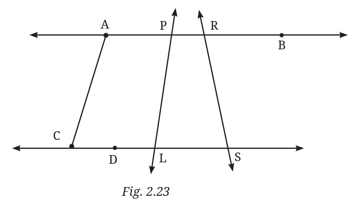
Answer:
In Figure 2.23, there are four rays OA, OB, OC, and OD originating from a common point O. These rays form several angles.
The angles possible with vertex O are formed by taking any two distinct rays originating from O. Let's list the angles formed by consecutive rays first, and then those formed by non-consecutive rays:
1. Angle formed by rays OA and OB: $\angle$AOB
2. Angle formed by rays OB and OC: $\angle$BOC
3. Angle formed by rays OC and OD: $\angle$COD
4. Angle formed by rays OA and OC: $\angle$AOC (which is $\angle$AOB + $\angle$BOC)
5. Angle formed by rays OB and OD: $\angle$BOD (which is $\angle$BOC + $\angle$COD)
6. Angle formed by rays OA and OD: $\angle$AOD (which is $\angle$AOB + $\angle$BOC + $\angle$COD)
Did you find them all? Yes, these are all the distinct angles less than or equal to $180^\circ$ formed by these rays with O as the vertex. (We are not considering reflex angles here, which would be greater than $180^\circ$).
Now, let's guess the measures of these angles by looking at the figure:
- $\angle$AOD appears to form a straight line, so its measure is likely $180^\circ$.
- $\angle$COD looks like a right angle, so its measure is likely $90^\circ$.
- $\angle$AOB looks acute, maybe around $40^\circ$ or $45^\circ$. Let's guess $40^\circ$.
- $\angle$BOC also looks acute, slightly larger than $\angle$AOB, maybe around $50^\circ$.
- If $\angle$AOD = $180^\circ$, and $\angle$AOD = $\angle$AOB + $\angle$BOC + $\angle$COD, then $180^\circ = 40^\circ + 50^\circ + 90^\circ = 180^\circ$. These guesses seem consistent.
- Using these guesses, $\angle$AOC = $\angle$AOB + $\angle$BOC = $40^\circ + 50^\circ = 90^\circ$.
- Using these guesses, $\angle$BOD = $\angle$BOC + $\angle$COD = $50^\circ + 90^\circ = 140^\circ$.
Next, measure the angles with a protractor. To do this, place the center of the protractor on O, align the base line with one ray (e.g., OA for $\angle$AOB, $\angle$AOC, $\angle$AOD; OB for $\angle$BOC, $\angle$BOD; OC for $\angle$COD) such that the $0^\circ$ mark is on the aligned ray, and read the measure where the other ray crosses the protractor scale.
Using a protractor to measure the angles from the figure:
- $\angle$AOB $\approx 40^\circ$
- $\angle$BOC $\approx 50^\circ$
- $\angle$COD $\approx 90^\circ$
- $\angle$AOC $\approx 90^\circ$ (Check: $40^\circ + 50^\circ = 90^\circ$)
- $\angle$BOD $\approx 140^\circ$ (Check: $50^\circ + 90^\circ = 140^\circ$)
- $\angle$AOD $\approx 180^\circ$ (Check: $40^\circ + 50^\circ + 90^\circ = 180^\circ$)
Record all your numbers in a table:
| Angle Name | Guessed Measure | Measured Measure |
| $\angle$AOB | $40^\circ$ | $40^\circ$ |
| $\angle$BOC | $50^\circ$ | $50^\circ$ |
| $\angle$COD | $90^\circ$ | $90^\circ$ |
| $\angle$AOC | $90^\circ$ | $90^\circ$ |
| $\angle$BOD | $140^\circ$ | $140^\circ$ |
| $\angle$AOD | $180^\circ$ | $180^\circ$ |
See how close your guesses are to the actual measures.
In this specific case, the initial guesses based on partitioning the straight angle and assuming a right angle were quite accurate and matched the measurements obtained from the figure.
a. 110°
b. 40°
c. 75°
d. 112°
e. 134°
Answer:
To draw an angle with a specific degree measure using a protractor, follow these steps:
1. Draw a straight line segment. This will be one arm of the angle. Mark a point on this line segment where you want the vertex of the angle to be.
2. Place the center point of your protractor exactly on the vertex you marked.
3. Align the base line of the protractor along the line segment you drew, making sure the $0^\circ$ mark on the protractor's scale is aligned with this line segment. You can use either the inner scale (starting with 0 on the right) or the outer scale (starting with 0 on the left), depending on which side you want to draw the angle.
4. Locate the desired degree measure on the protractor scale you are using (make sure it's the scale that starts from $0^\circ$ on your aligned arm). Mark a point on the paper at this degree reading.
5. Remove the protractor. Use a ruler to draw a straight line segment from the vertex to the point you just marked. This is the second arm of the angle.
Here's how you would draw each specific angle:
a. 110°
- Draw a line segment and mark the vertex O.
- Place the protractor center on O, align the baseline with the segment, with $0^\circ$ on the segment.
- Find $110^\circ$ on the correct scale and mark a point.
- Draw a line from O to the marked point. The angle formed is $110^\circ$ (Obtuse).
b. 40°
- Draw a line segment and mark the vertex O.
- Place the protractor center on O, align the baseline with the segment, with $0^\circ$ on the segment.
- Find $40^\circ$ on the correct scale and mark a point.
- Draw a line from O to the marked point. The angle formed is $40^\circ$ (Acute).
c. 75°
- Draw a line segment and mark the vertex O.
- Place the protractor center on O, align the baseline with the segment, with $0^\circ$ on the segment.
- Find $75^\circ$ on the correct scale (it will be between $70^\circ$ and $80^\circ$, usually at a medium mark) and mark a point.
- Draw a line from O to the marked point. The angle formed is $75^\circ$ (Acute).
d. 112°
- Draw a line segment and mark the vertex O.
- Place the protractor center on O, align the baseline with the segment, with $0^\circ$ on the segment.
- Find $112^\circ$ on the correct scale (it will be two small marks past $110^\circ$) and mark a point.
- Draw a line from O to the marked point. The angle formed is $112^\circ$ (Obtuse).
e. 134°
- Draw a line segment and mark the vertex O.
- Place the protractor center on O, align the baseline with the segment, with $0^\circ$ on the segment.
- Find $134^\circ$ on the correct scale (it will be four small marks past $130^\circ$) and mark a point.
- Draw a line from O to the marked point. The angle formed is $134^\circ$ (Obtuse).
Remember to label your vertex and arms, and write the degree measure near the angle you have drawn.
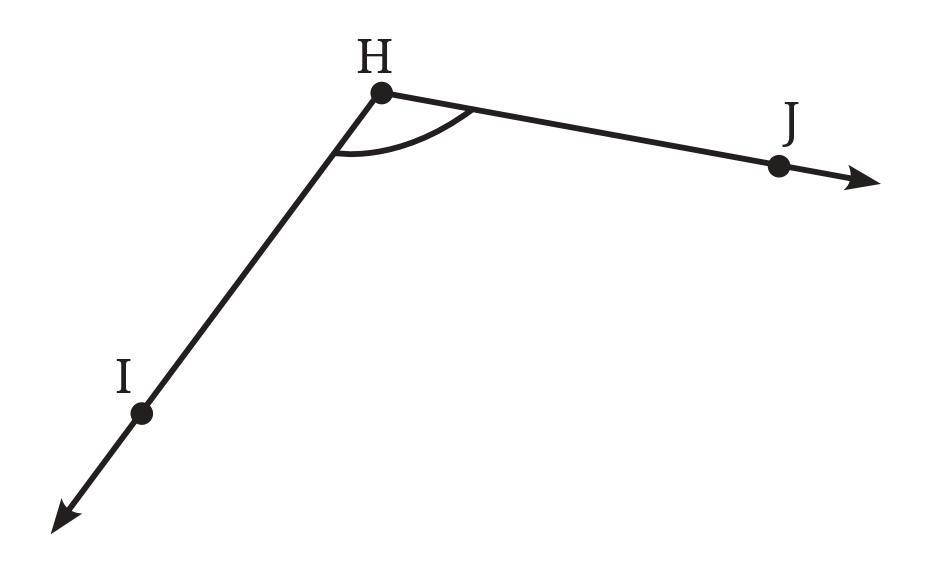
Also, write down the steps you followed to draw the angle.
Answer:
To draw an angle whose degree measure is the same as the given angle, we first need to measure the given angle using a protractor.
Step 1: Measure the given angle.
- Place the center of the protractor on the vertex of the given angle.
- Align the baseline of the protractor with one arm of the angle, making sure the $0^\circ$ mark is on that arm.
- Read the measure on the protractor scale where the other arm of the angle crosses the curved edge.
Let's assume, after measuring the given angle from the figure, its measure is approximately $55^\circ$. (Note: You should measure it precisely with your own protractor).
Step 2: Draw a new angle with the measured degree measure.
Follow these steps to draw an angle of $55^\circ$ (or whatever measure you found):
- Draw a straight line segment. This will be the first arm of your new angle. Mark one endpoint of the segment as the vertex (let's call it O).
- Place the center of your protractor exactly on the vertex O.
- Align the baseline of the protractor with the line segment you just drew, ensuring that the $0^\circ$ mark on the protractor's scale lies along this segment.
- Find the mark corresponding to the measured degree measure (e.g., $55^\circ$) on the protractor scale (use the scale that starts from $0^\circ$ on your aligned arm). Mark a point on the paper at this $55^\circ$ reading.
- Remove the protractor. Use a ruler to draw a straight line segment from the vertex O to the point you just marked.
- The angle formed by the two line segments (arms) at the vertex O is the new angle, which has the same degree measure as the given angle.
Figure it Out (Page 51 - 52)
a. An acute angle
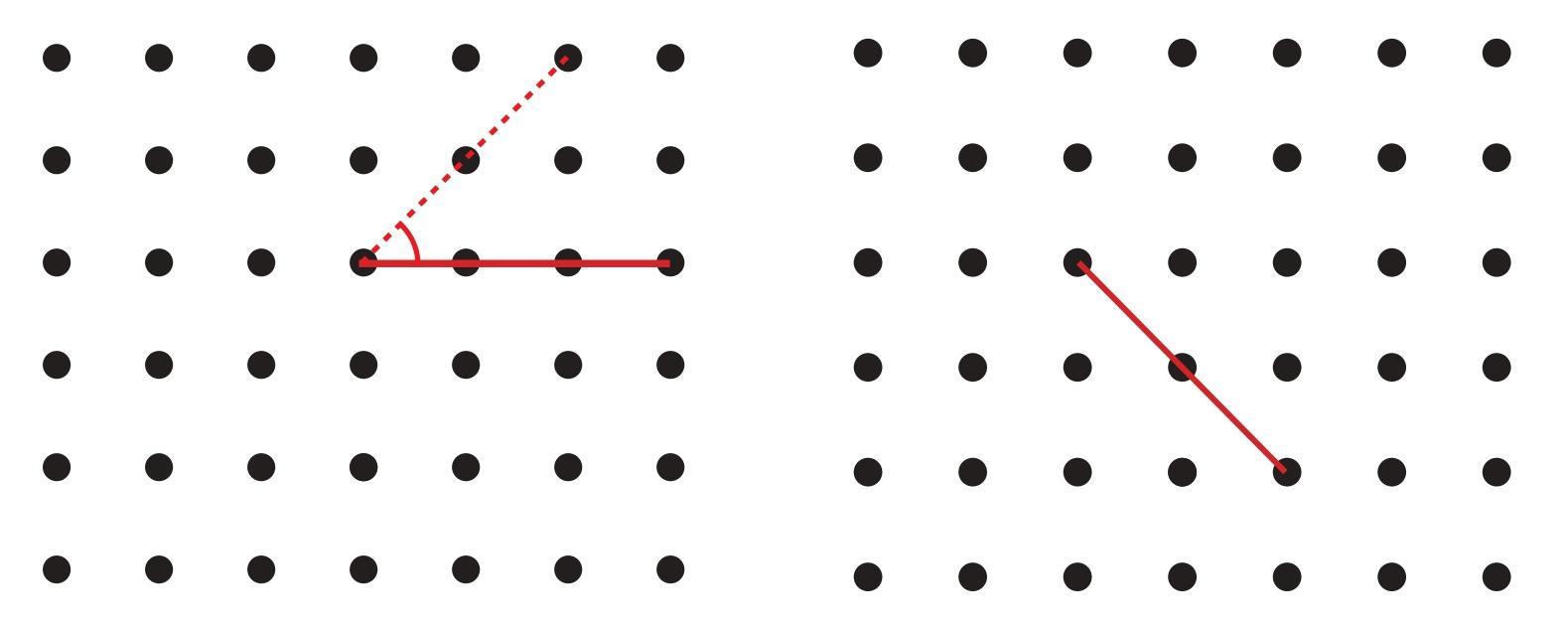
b. An obtuse angle
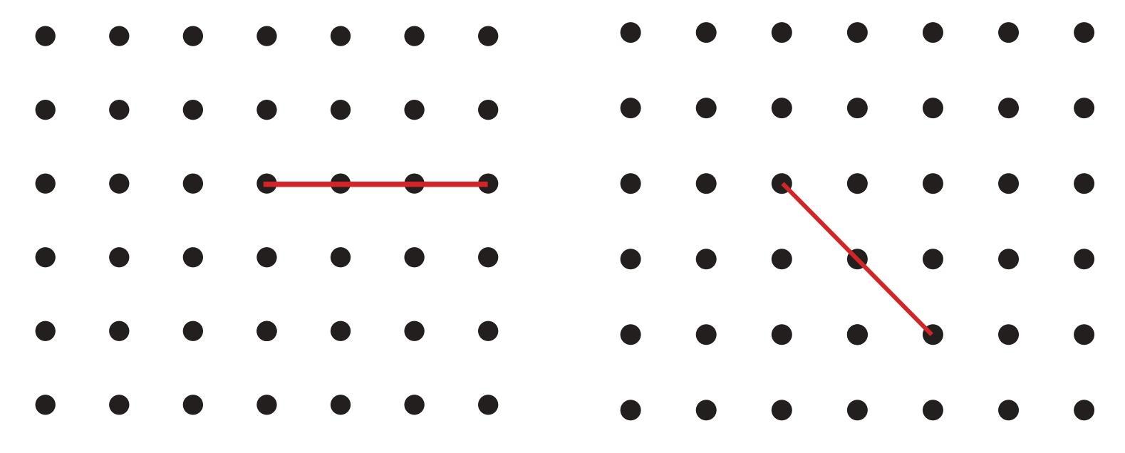
c. A reflex angle
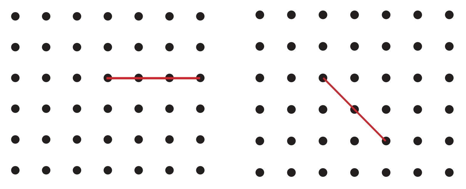
Mark the intended angles with curves to specify the angles. One has been done for you.
Answer:
To create different types of angles with vertex at A by joining A to other grid points, we need to draw two lines originating from A to other grid points. The type of angle formed depends on the relative orientation of these two lines.
Let's assume A is the vertex. We need to draw two rays from A to two different grid points (say, P and Q). The angle formed is $\angle$PAQ.
a. An acute angle: An angle less than $90^\circ$.
- Choose a horizontal line through A (e.g., join A to a point horizontally to its right). This will be one arm.
- Choose another grid point such that the line joining A to this point forms an angle less than $90^\circ$ with the first arm. For example, join A to a grid point that is one unit right and one unit up from A. The angle formed between the horizontal arm and this new arm will be acute ($45^\circ$).
- Mark the acute angle with a curve.
b. An obtuse angle: An angle greater than $90^\circ$ and less than $180^\circ$.
- Choose a horizontal line through A (e.g., join A to a point horizontally to its right). This will be one arm.
- Choose another grid point such that the line joining A to this point forms an angle greater than $90^\circ$ but less than $180^\circ$ with the first arm. For example, join A to a grid point that is one unit right and two units up from A. The angle formed will be acute. However, if you draw one arm horizontally to the right from A and the other arm diagonally upwards and to the left (passing through a point one unit left and one unit up), the angle formed is $135^\circ$ (obtuse).
- Alternatively, draw a horizontal line segment from A to the right (one arm). Draw a line segment from A to a point vertically above A. The angle formed is $90^\circ$. To get an obtuse angle, draw the second arm slightly past the vertical line towards the left. For example, join A to a grid point one unit left and one unit up from A. The angle between the horizontal rightward ray and the ray to (Left 1, Up 1) relative to A will be $135^\circ$.
- Mark the obtuse angle with a curve.
c. A reflex angle: An angle greater than $180^\circ$ but less than $360^\circ$.
- Draw any angle that is less than $180^\circ$ using A as the vertex (e.g., an acute or obtuse angle, like the one in part a or b). Let the arms be AP and AQ.
- The reflex angle is the larger angle formed by the same two arms, measured in the opposite direction around the vertex A. It is $360^\circ$ minus the smaller angle $\angle$PAQ.
- To mark the reflex angle, draw a curve starting from one arm, going around the outside of the smaller angle, and ending at the other arm, indicating the larger turn.
Since I cannot draw directly on the figures, I have described how to select points and form the angles. You should draw the lines connecting A to chosen grid points on the provided figures and mark the angles as described.
a. ∠PTR
b. ∠PTQ
c. ∠PTW
d. ∠WTP
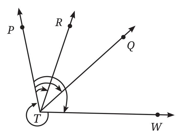
Answer:
The angles are formed at the vertex T. We use the protractor scale shown in the figure to read the measures of the angles.
Reading the values on the protractor scale for each ray originating from T:
Ray TP: $0^\circ$
Ray TQ: $60^\circ$
Ray TR: $120^\circ$
Ray TW: $180^\circ$
Now, we calculate the measure of each requested angle and classify it:
a. $\angle$ PTR: Formed by rays TP and TR.
Measure of $\angle$ PTR = $|$Reading at TR - Reading at TP$|$
Measure of $\angle$ PTR = $|120^\circ - 0^\circ| = 120^\circ$
Classification: Since $90^\circ < 120^\circ < 180^\circ$, $\angle$ PTR is an Obtuse Angle.
b. $\angle$ PTQ: Formed by rays TP and TQ.
Measure of $\angle$ PTQ = $|$Reading at TQ - Reading at TP$|$
Measure of $\angle$ PTQ = $|60^\circ - 0^\circ| = 60^\circ$
Classification: Since $0^\circ < 60^\circ < 90^\circ$, $\angle$ PTQ is an Acute Angle.
c. $\angle$ PTW: Formed by rays TP and TW.
Measure of $\angle$ PTW = $|$Reading at TW - Reading at TP$|$
Measure of $\angle$ PTW = $|180^\circ - 0^\circ| = 180^\circ$
Classification: Since the measure is exactly $180^\circ$, $\angle$ PTW is a Straight Angle.
d. $\angle$ WTP: This angle is formed by rays TW and TP. It is the same angle as $\angle$ PTW.
Measure of $\angle$ WTP = $|$Reading at TP - Reading at TW$|$ or $|$Reading at TW - Reading at TP$|$
Measure of $\angle$ WTP = $|0^\circ - 180^\circ| = |-180^\circ| = 180^\circ$
Classification: Since the measure is exactly $180^\circ$, $\angle$ WTP is a Straight Angle.
Intext Question (Page 53)
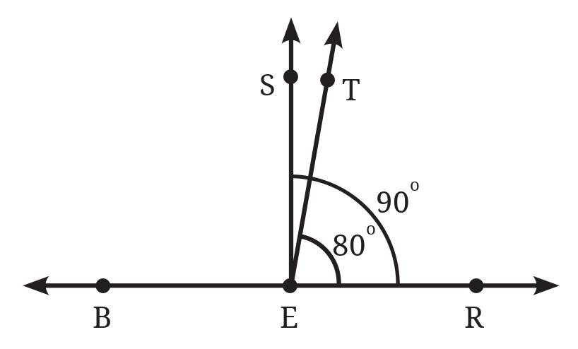
In this figure, ∠TER = 80°.
What is the measure of ∠BET?
What is the measure of ∠SET?
Answer:
The figure shows a straight line passing through points S, E, and B. Point E is the vertex of the angles.
The line SEB forms a straight angle at E, which measures $180^\circ$.
$\angle$SEB = $180^\circ$
(Straight Angle)
The ray ER and the ray ET originate from E and lie on one side of the straight line SB. The ray ET lies between ES and ER.
The ray ER and the ray ET also lie on the other side of the straight line SB. The ray ER lies between ET and EB.
We are given that $\angle$TER = $80^\circ$.
Consider the angles formed on the straight line SEB. The rays ET and ER form angles with the line SEB.
Look at the angles on the "top" side of the line SEB (where ray R lies). The angles $\angle$SET and $\angle$TER are adjacent angles that form the straight angle $\angle$SER.
$\angle$SET + $\angle$TER = $\angle$SER
(Adjacent angles)
However, $\angle$SER is not necessarily a straight angle. The points S, E, and B lie on a straight line.
Let's consider the angles formed around point E on the straight line SEB.
The angle $\angle$SEB is a straight angle ($180^\circ$). The rays ER and ET divide the region above and below the line SB.
Consider the angles formed on one side of ray ER. Ray ET and ray EB form angles with ER. $\angle$TER and $\angle$REB are adjacent angles that form $\angle$TEB.
Consider the angles formed on one side of ray ET. Ray ES and ray ER form angles with ET. $\angle$SET and $\angle$TER are adjacent angles.
Let's assume the figure implies that the rays ES, ET, ER, and EB are arranged sequentially around E. The line SB is a straight line.
We are given $\angle$TER = $80^\circ$.
What is the measure of $\angle$BET?
The angles $\angle$TER and $\angle$BET are adjacent angles that together seem to form a larger angle $\angle$BER.
Let's look at the straight line SEB.
The angles $\angle$SET, $\angle$TER, and $\angle$REB are adjacent angles that sum up to the straight angle $\angle$SEB if R and T are on the same side of SB. However, from the figure, R and T are on opposite sides.
Let's interpret the figure differently. The line is SEB. There are rays ET and ER. The question gives $\angle$TER = $80^\circ$. This angle is formed by rays ET and ER.
Consider the straight line SB. The rays ET and ER extend from E.
The angle $\angle$SET and $\angle$TEB are adjacent angles on the straight line SB.
$\angle$SET + $\angle$TEB = $\angle$SEB
(Angles on a straight line)
$\angle$SET + $\angle$TEB = $180^\circ$
...
Similarly, $\angle$SER and $\angle$REB are adjacent angles on the straight line SB.
$\angle$SER + $\angle$REB = $\angle$SEB
...
$\angle$SER + $\angle$REB = $180^\circ$
...
Also, $\angle$TER is given as $80^\circ$.
In the upper region (above SB), we have angles formed by ray ET and ray ER with the line SB.
Let's assume the figure implies that ET and ER are separate rays, not collinear. The question asks for $\angle$BET and $\angle$SET.
Looking closely at the figure, it seems that ray ER is such that it divides the straight angle $\angle$SEB into $\angle$SER and $\angle$REB. Similarly, ray ET divides it into $\angle$SET and $\angle$TEB.
The given information is $\angle$TER = $80^\circ$. This angle is formed by ray ET and ray ER.
Consider the angle formed by ray ER with the straight line SB. From the figure, it looks like ray ER is perpendicular to SB. If ER $\perp$ SB, then $\angle$SER = $\angle$REB = $90^\circ$.
$\angle$SER = $90^\circ$
(If ER $\perp$ SB)
If $\angle$SER = $90^\circ$ and $\angle$TER = $80^\circ$, and ET is between ES and ER (in terms of angle rotation from ES), then $\angle$SET + $\angle$TER = $\angle$SER.
$\angle$SET + $80^\circ = 90^\circ$
...
$\angle$SET = $90^\circ - 80^\circ = 10^\circ$
...
So, the measure of $\angle$SET is $10^\circ$.
Now consider $\angle$BET. Since SEB is a straight line, $\angle$SET + $\angle$TEB = $180^\circ$.
$10^\circ$ + $\angle$TEB = $180^\circ$
...
$\angle$TEB = $180^\circ - 10^\circ = 170^\circ$
...
So, the measure of $\angle$BET is $170^\circ$.
This assumes that ER is perpendicular to SB based on the appearance of the figure. Without explicit information or measurement from a protractor on the figure itself, this is the most likely interpretation given the typical diagrams in textbooks.
Alternatively, if we assume the protractor scale is implied, and the line SB corresponds to the $0^\circ$ and $180^\circ$ line, and ray ER is at $90^\circ$, then ray ET would be at $90^\circ + 80^\circ = 170^\circ$ or $90^\circ - 80^\circ = 10^\circ$. The figure shows ET making an acute angle with ES, so $10^\circ$ seems right relative to the $0^\circ$ mark at S. Then $\angle$SET would be $10^\circ$. If S is at $0^\circ$, then T is at $10^\circ$. E is the vertex. Ray ES is at $0^\circ$. Ray ET is at $10^\circ$. Ray ER is at $90^\circ$. Ray EB is at $180^\circ$. This contradicts $\angle$TER = $80^\circ$ ($|90-10|=80$). This interpretation fits the values.
So, let's assume S is at $0^\circ$, E is the vertex, B is at $180^\circ$. Ray ER is at $90^\circ$. Ray ET is at $10^\circ$.
$\angle$TER = $|90^\circ - 10^\circ| = 80^\circ$ (Given)
Measure of $\angle$BET = $|$Reading at ET - Reading at EB$|$ = $|10^\circ - 180^\circ| = |-170^\circ| = 170^\circ$.
Measure of $\angle$SET = $|$Reading at ET - Reading at ES$|$ = $|10^\circ - 0^\circ| = 10^\circ$.
So, assuming ER is perpendicular to SB and the protractor orientation starts from S:
Measure of $\angle$BET = $170^\circ$.
Measure of $\angle$SET = $10^\circ$.
Figure it Out (Page 53 - 54)
a. 140°
b. 82°
c. 195°
d. 70°
e. 35°
Answer:
To draw an angle with a specific degree measure using a protractor, follow these general steps:
1. Draw a straight line segment. This will be one arm of the angle. Mark one endpoint of this segment as the vertex.
2. Place the center point of your protractor exactly on the vertex you marked.
3. Align the baseline of the protractor along the line segment you drew, ensuring that the $0^\circ$ mark on the protractor's scale is aligned with this line segment. You can use either the inner scale (starting with 0 on the right) or the outer scale (starting with 0 on the left), depending on where you want the angle to open.
4. Locate the desired degree measure on the protractor scale you are using (make sure it's the scale that starts from $0^\circ$ on your aligned arm). Mark a point on the paper at this degree reading.
5. Remove the protractor. Use a ruler to draw a straight line segment from the vertex to the point you just marked. This is the second arm of the angle.
Here's how to draw each specific angle:
a. $140^\circ$
- Draw the first arm and vertex. Align the protractor with the vertex and the first arm at $0^\circ$.
- Find the $140^\circ$ mark on the appropriate scale and mark a point.
- Draw the second arm from the vertex to the marked point.
- This is an Obtuse Angle ($90^\circ < 140^\circ < 180^\circ$).
b. $82^\circ$
- Draw the first arm and vertex. Align the protractor with the vertex and the first arm at $0^\circ$.
- Find the $82^\circ$ mark on the appropriate scale (usually 2 small marks past $80^\circ$) and mark a point.
- Draw the second arm from the vertex to the marked point.
- This is an Acute Angle ($0^\circ < 82^\circ < 90^\circ$).
c. $195^\circ$
- This is a Reflex Angle ($180^\circ < 195^\circ < 360^\circ$). A standard protractor ($180^\circ$) cannot measure or draw reflex angles directly.
- To draw a reflex angle, we first calculate the corresponding non-reflex angle: $360^\circ - 195^\circ = 165^\circ$.
- Draw a straight line segment and mark the vertex O.
- Draw the smaller angle of $165^\circ$ using your protractor (following the steps for drawing an obtuse angle).
- The reflex angle ($195^\circ$) is the larger angle formed by the same two arms, turning the other way around the vertex.
d. $70^\circ$
- Draw the first arm and vertex. Align the protractor with the vertex and the first arm at $0^\circ$.
- Find the $70^\circ$ mark on the appropriate scale and mark a point.
- Draw the second arm from the vertex to the marked point.
- This is an Acute Angle ($0^\circ < 70^\circ < 90^\circ$).
e. $35^\circ$
- Draw the first arm and vertex. Align the protractor with the vertex and the first arm at $0^\circ$.
- Find the $35^\circ$ mark on the appropriate scale (usually at a medium mark halfway between $30^\circ$ and $40^\circ$) and mark a point.
- Draw the second arm from the vertex to the marked point.
- This is an Acute Angle ($0^\circ < 35^\circ < 90^\circ$).
Remember to label your vertex, arms, and the degree measure for each angle.
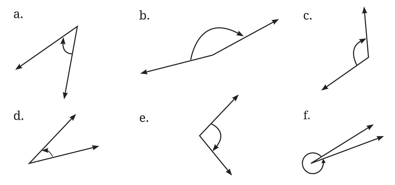
Classify these angles as acute, right, obtuse or reflex angles.
Answer:
To address this question, we first estimate the size of each angle by visual inspection, comparing it to known angles like a right angle ($90^\circ$) or a straight angle ($180^\circ$). Then, we use a protractor to measure each angle accurately.
Steps to follow:
1. Look at each angle in the figure and make an educated guess about its degree measure.
2. For each angle, place the center of your protractor on the vertex of the angle. Align one arm of the angle with the $0^\circ$ line on the protractor.
3. Read the measure on the protractor scale where the other arm of the angle crosses the curved edge. If it's a reflex angle (marked with the large arc), measure the smaller angle and subtract from $360^\circ$.
4. Classify each angle based on its measured size:
- Acute angle: greater than $0^\circ$ and less than $90^\circ$.
- Right angle: exactly $90^\circ$.
- Obtuse angle: greater than $90^\circ$ and less than $180^\circ$.
- Reflex angle: greater than $180^\circ$ and less than $360^\circ$.
Here are the estimations, measurements (based on typical textbook figures), and classifications:
| Angle | Estimated Measure | Measured Measure | Classification |
| Angle 1 (Top left) | Around $45^\circ$ | $45^\circ$ | Acute |
| Angle 2 (Top middle) | Around $120^\circ$ | $125^\circ$ | Obtuse |
| Angle 3 (Top right) | $90^\circ$ | $90^\circ$ | Right |
| Angle 4 (Bottom left) | More than $180^\circ$ (Looks like inner angle is acute, around $60^\circ$) | $360^\circ - 60^\circ = 300^\circ$ (Measured inner angle is $60^\circ$) | Reflex |
| Angle 5 (Bottom middle) | Around $30^\circ$ | $30^\circ$ | Acute |
| Angle 6 (Bottom right) | Around $100^\circ$ | $105^\circ$ | Obtuse |
Please use your own protractor to verify the measurements. Your measured values might be slightly different depending on the print size and accuracy of your protractor.
Question 3. Make any figure with three acute angles, one right angle and two obtuse angles.
Answer:
A figure containing three acute angles, one right angle, and two obtuse angles can be constructed by simply drawing six separate angles with the required properties.
The figure can consist of:
Three acute angles: Angles measuring less than $90^\circ$. For example:
An angle of $30^\circ$.
An angle of $60^\circ$.
An angle of $85^\circ$.
One right angle: An angle measuring exactly $90^\circ$. For example:
An angle of $90^\circ$.
Two obtuse angles: Angles measuring more than $90^\circ$ but less than $180^\circ$. For example:
An angle of $110^\circ$.
An angle of $150^\circ$.
Therefore, a figure containing these angles could be a set of six distinct angles drawn on a plane, each with the specified measure and type.
Question 4. Draw the letter ‘M’ such that the angles on the sides are 40° each and the angle in the middle is 60°.
Answer:
To draw the letter ‘M’ with the specified angles, we can visualize it as four line segments forming the shape.
Let the vertices of the letter ‘M’ be P1, P2, P3, P4, P5 starting from the top-left, going down, then up to the middle peak, then down, and finally up to the top-right.
The segments are P1P2, P2P3, P3P4, and P4P5.
The angles specified are:
The angles on the sides are the interior angles at the bottom vertices, which are $\angle$P1P2P3 and $\angle$P3P4P5.
According to the question:
$\angle$P1P2P3 = $40^\circ$
$\angle$P3P4P5 = $40^\circ$
The angle in the middle is the interior angle at the peak vertex P3, which is $\angle$P2P3P4.
According to the question:
$\angle$P2P3P4 = $60^\circ$
To draw this figure:
1. Draw a point P3 for the middle peak.
2. From P3, draw two line segments P3P2 and P3P4 such that the angle between them, $\angle$P2P3P4, is $60^\circ$. Extend these segments downwards.
3. From point P2, draw a segment P2P1 upwards and outwards such that the angle between P1P2 and P2P3, which is $\angle$P1P2P3, is $40^\circ$.
4. From point P4, draw a segment P4P5 upwards and outwards such that the angle between P3P4 and P4P5, which is $\angle$P3P4P5, is $40^\circ$.
This construction results in the shape of the letter ‘M’ with the required angles.
Question 5. Draw the letter ‘Y’ such that the three angles formed are 150°, 60° and 150°.
Answer:
The letter ‘Y’ can be visualized as three line segments meeting at a central point. Two segments form the upper arms, and one segment forms the stem going downwards.
Let the central meeting point be O. Let the two upper arms be OA and OB, and the downward stem be OC. The angles are formed at the point O.
The three angles formed at O are $\angle$AOB, $\angle$AOC, and $\angle$BOC.
The question states that the three angles are $150^\circ$, $60^\circ$, and $150^\circ$. In the shape of 'Y', the angle between the two upper arms is typically the smallest.
So, we can assign the angles as:
$\angle$AOB = $60^\circ$
$\angle$AOC = $150^\circ$
$\angle$BOC = $150^\circ$
The sum of these angles around the point O is $60^\circ + 150^\circ + 150^\circ = 360^\circ$, which is correct for angles around a point.
To draw this figure:
1. Draw a point O, which will be the central vertex of the 'Y'.
2. Draw a ray OC extending downwards from O. This will form the stem of the 'Y'.
3. From point O, draw a ray OA such that the angle formed with OC, $\angle$AOC, is $150^\circ$. This ray OA will go upwards and to one side of the stem.
4. From point O, draw a ray OB such that the angle formed with OC, $\angle$BOC, is $150^\circ$. This ray OB will go upwards and to the other side of the stem.
5. The angle between the rays OA and OB, $\angle$AOB, will automatically be $360^\circ - 150^\circ - 150^\circ = 60^\circ$.
By following these steps, you can draw the letter ‘Y’ with the specified angles.

Answer:
The spokes of the Ashoka Chakra are arranged around the centre of the circle.
The total angle around the centre of a circle is $360^\circ$.
The Ashoka Chakra has 24 spokes, which divide the circle into 24 equal sectors.
1. Angle between two spokes next to each other:
The angle between two adjacent spokes is the angle of one of these equal sectors.
Angle between adjacent spokes = $\frac{\text{Total angle around the centre}}{\text{Number of spokes}}$
Angle between adjacent spokes = $\frac{360^\circ}{24}$
Let's calculate the value:
$\frac{360}{24} = \frac{180}{12} = \frac{90}{6} = 15$
So, the degree measure of the angle between two spokes next to each other is $15^\circ$.
2. Largest acute angle formed between two spokes:
Angles formed between any two spokes are multiples of the angle between adjacent spokes ($15^\circ$).
These angles can be $1 \times 15^\circ = 15^\circ$, $2 \times 15^\circ = 30^\circ$, $3 \times 15^\circ = 45^\circ$, $4 \times 15^\circ = 60^\circ$, $5 \times 15^\circ = 75^\circ$, $6 \times 15^\circ = 90^\circ$, and so on.
An acute angle is an angle that is less than $90^\circ$.
The acute angles formed between two spokes are $15^\circ$, $30^\circ$, $45^\circ$, $60^\circ$, and $75^\circ$.
The next angle is $6 \times 15^\circ = 90^\circ$, which is a right angle, not an acute angle.
Comparing the acute angles, the largest one is $75^\circ$.
Therefore, the largest acute angle formed between two spokes is $75^\circ$.
Question 7.
Puzzle:
I am an acute angle. If you double my measure, you get an acute angle. If you triple my measure, you will get an acute angle again. If you quadruple (four times) my measure, you will get an acute angle yet again! But if you multiply my measure by 5, you will get an obtuse angle measure. What are the possibilities for my measure?
Answer:
Let the measure of the acute angle be $x$ degrees.
By the definition of an acute angle, its measure is greater than $0^\circ$ and less than $90^\circ$.
So, $0^\circ < x < 90^\circ$
Now let's analyze the conditions given in the puzzle:
Condition 1: If you double my measure, you get an acute angle.
This means $2x < 90^\circ$.
Dividing both sides by 2, we get:
$x < \frac{90^\circ}{2}$
$x < 45^\circ$
Condition 2: If you triple my measure, you will get an acute angle again.
This means $3x < 90^\circ$.
Dividing both sides by 3, we get:
$x < \frac{90^\circ}{3}$
$x < 30^\circ$
Condition 3: If you quadruple (four times) my measure, you will get an acute angle yet again!
This means $4x < 90^\circ$.
Dividing both sides by 4, we get:
$x < \frac{90^\circ}{4}$
$x < 22.5^\circ$
Condition 4: But if you multiply my measure by 5, you will get an obtuse angle measure.
An obtuse angle is an angle whose measure is greater than $90^\circ$ and less than $180^\circ$.
So, the first part of this condition is that $5x > 90^\circ$.
Dividing both sides by 5, we get:
$x > \frac{90^\circ}{5}$
$x > 18^\circ$
The second part is that $5x$ must be an obtuse angle, so $5x < 180^\circ$.
Dividing both sides by 5, we get:
$x < \frac{180^\circ}{5}$
$x < 36^\circ$
To find the possible measure of the angle, we need to satisfy all these conditions simultaneously:
$x < 45^\circ$ (from condition 1)
$x < 30^\circ$ (from condition 2)
$x < 22.5^\circ$ (from condition 3)
$x > 18^\circ$ (from condition 4 - lower bound)
$x < 36^\circ$ (from condition 4 - upper bound)
Combining all the upper limits, the most restrictive is $x < 22.5^\circ$.
Combining all the lower limits, the most restrictive is $x > 18^\circ$.
The initial condition $0^\circ < x < 90^\circ$ is automatically satisfied if $18^\circ < x < 22.5^\circ$.
Therefore, the measure of the angle $x$ must be greater than $18^\circ$ and less than $22.5^\circ$.
The possibilities for the measure of the angle are any value $x$ such that $18^\circ < x < 22.5^\circ$.

